When I was young, attending the Remembrance Sunday parade as an Air Cadet was mandatory. I remember the cold November mornings, but it wasn’t emotional for me, aside from seeing people who had lived through it.
As an adult, the ceremony has more meaning. Over time, I’ve built a connection to the past, and watching war films often leaves me wondering why others don’t seem to feel the same impact. Whilst film is usually fiction, these events were real. These were real people, young men with families, whose sacrifices gave us the freedoms we enjoy today. Many from my generation and younger seem disconnected from that understanding. They don’t seem to have any more meaning that a character from a Marvel movie or a drawing of a Roman soldier in a book.
Whether films are accurate or not, it can leave you with something to think about and try to imagine the situation these people found themselves in. A powerful reminder for me comes from the final scene of Blackadder Goes Forth. Set in 1917, the series follows British soldiers in the trenches. We get to know them, their characters and realise they are individuals, each with complex lives – they are not just a number or a name on a cenotaph. In the end, they are sent over the top, and the scene fades from the chaos an incessant noise of gunfire and bombs on no-mans-land to a peaceful field of red poppies and birdsong. To me this means that whilst memories fade, this beautiful land we take for granted came at great cost. While not historically accurate, this scene makes the human cost of war painfully real.
Whilst many films were made about ww2 and to a lesser extent ww1, we’d do well to remember that terrible war atrocities are not the thing of the past we might like to think they are. In 2002, I visited Bosnia as part of the ICMP, working to repatriate the missing from mass graves. Seeing bodies wearing Nike trainers and and wearing watches that are still ticking made it clear these tragedies are not distant. All this made the film ‘Behind enemy lines’ set in the same region at the same time, very much more personal. Because no matter how the film may portray the human cost it actually doesn’t come even remotely close. This, along with recent conflicts in the Middle East, resonates even more deeply now that I have my own children.
It really is crucially important to try remember the fallen and also that peace is a fragile thing. We are fortunate to have lived here in the UK in a relatively peaceful time, but war still rages.
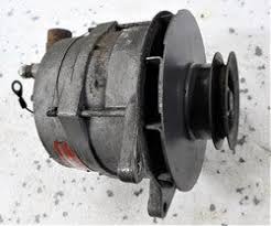
The aviation industry might make you think that aircraft alternators are made out of special materials, have been tested to impeccable standards and are manufactured on special production lines sprinkled with pixie dust. A normal engineer couldn’t hope to service one. The reality is that they are 1950’s or 1960’s American car (like Ford) alternators that wouldn’t stand up to the quality, power output or or rigours of a modern car alternator. Modern car alternators can produce a smooth output from 750 to 6000 rpm with little or no noise in the output because the tolerances and power electronics / frequency are far more advanced.
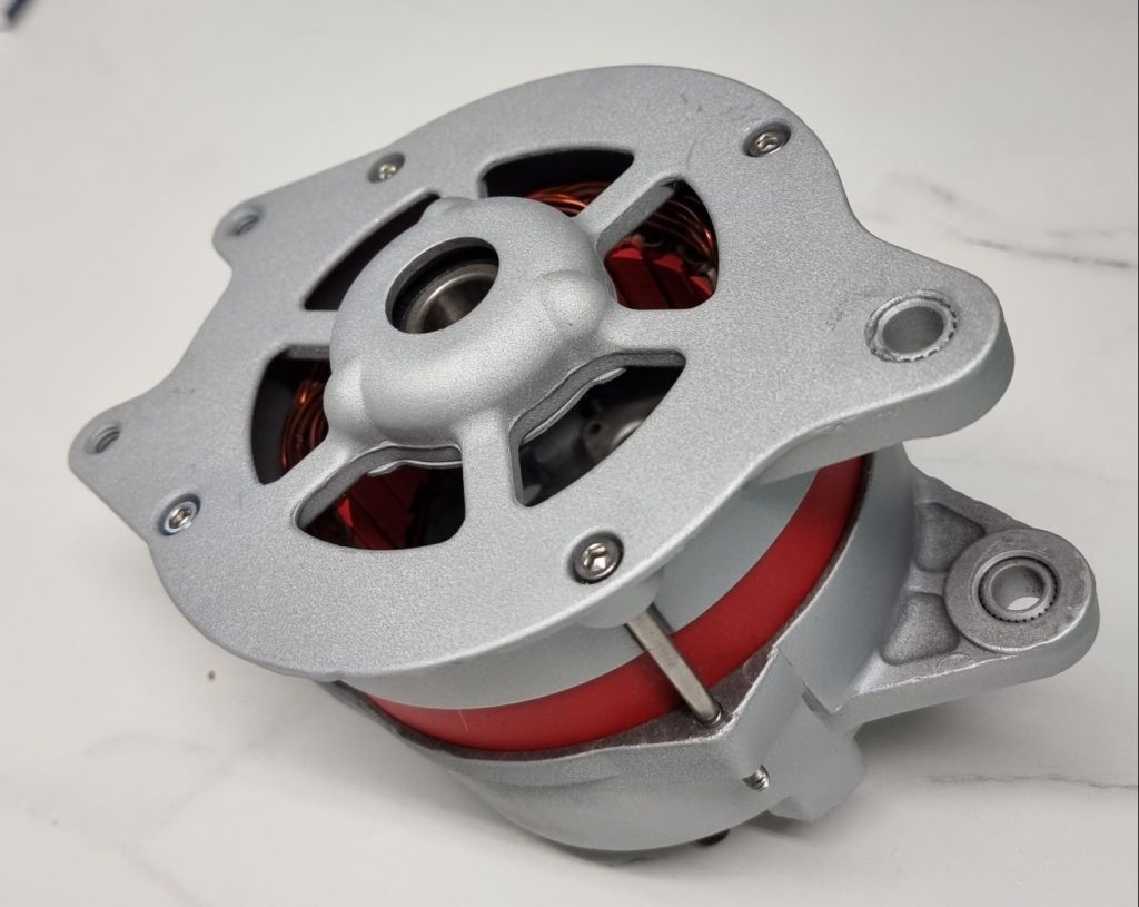
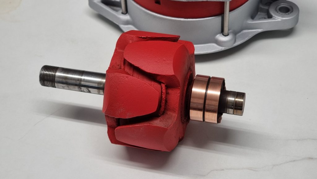
Mid overhaul, rotor shaft removed. The red ring is the laminated stator ring. The top casting has a simple sealed ball bearing and the rear casting contains a roller bearing. The through bolts contain 2mm holes cross-drilled at the end of the thread for lock wire. (actually the same alternator as first figure)
Basic Operation
Prestolite Maintenance Manual
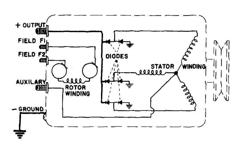
The principle of operation is simple, a rotating magnet induces an alternating current in a stator winding (hence the name alternator) that is then rectified and delivered to the battery.
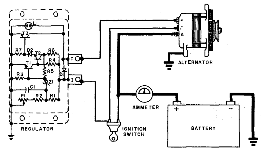
The figure above shows the schematic layout. The stator would work with a single coil but by arranging 3 at 120 degrees (equally around the circle) the sine waves from each phase sums to a smooth output. In theory it shouldn’t whine or produce large amounts of ripple or pulse. This 3-phase approach also doesn’t require a return path at the centre of all 3 connected coils because each phase works against the other two. The aux output (at the centre of the windings) isn’t required and can be left unconnected.
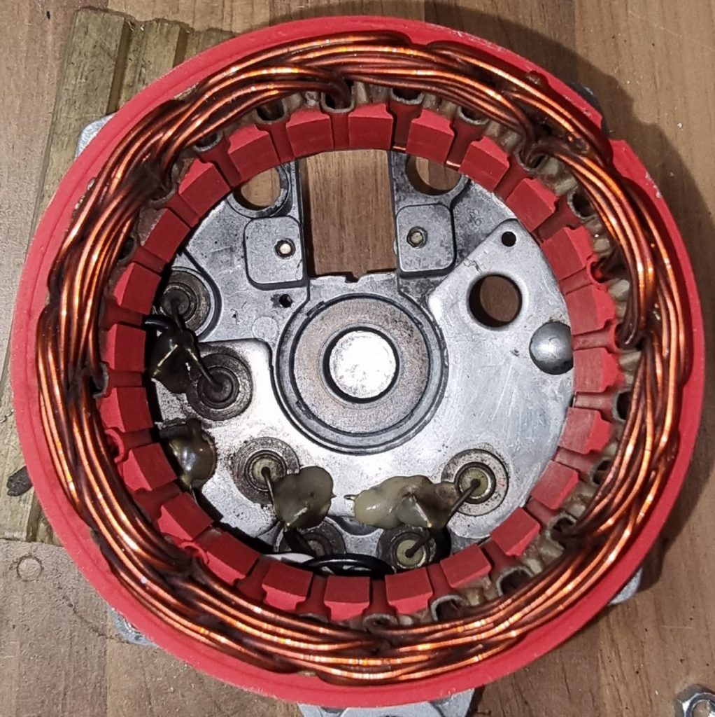
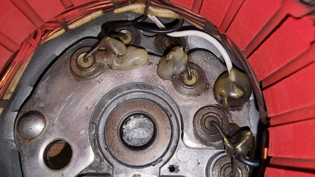
Stator windings. The bearing at the bottom. The stator is laminated steel which helps control eddy currents increasing efficiency. The round things are diodes of which there are 6 because its a 3-phase rectifier. rectifier plate mounted at the end. The plate is the output of the positive end of the diodes which leave via the output terminal (left) the other 3 diodes go to ground which is the alternator casing (top two and bottom right). The white wire is tied to the centre of the 3 coils which leaves to the aux terminal which is isolated from the rectifier plate. One or two needle bearings are visible in the bearing (centre) and the black ring is an oil grease seal.
Regulation
We said that all we do is swing a magnet around in a coil to produce our output but obviously, there is more to it because that would overcharge the battery. If an alternator became detached from the battery, the output voltage may reach hundreds of volts.
Aircraft alternator regulators tend to be very simple on or off affairs and the electric regulators are in some cases mechanical. They are unreliable to the point that its typical to include an over voltage relay (OVR) which cuts off excitation completely if a preset output voltage is exceeded. For a 14V system this would typically be set to 16V. If the system reached 16V the relay will latch on turning the alternator off.
To regulate the alternator output we want a variable strength magnet in the rotor instead of a permanent magnet. In an alternator the rotor is an electromagnet and when the battery is low the strength of this magnet is high and when the battery is fully charged the magnet is its weakest and its the job of the regulator to control this. In a car this will be built into the alternator and it will use fast modulation of the rotor current in a closed control loop to produce an output that is always spot on. In an aircraft regulators tend to be separate units like they used to be in cars. In cars they stopped doing that because regulation control is poor, being affected by voltage drops, stray magnetic fields and radio interference as well as emitting radio interference all over the place. What normally happens when there is parasitic resistance is that the voltage will fluctuate, often oscillating, but even under the best situation its poor.
The rotor. The slip rings (copper coloured) connect a single winding axially wound around the centre former. The windings are visible.
An electromagnet is just a winding, and winding around an iron core concentrates the field. As such, the rotor is a single winding around an iron former. The two interlocking sets of fingers are opposing poles (each end) of the electromagnet which means that the rotor actually has alternating N-S-N-S… arrangement. As we can see in the picture, one finger is part of one end and the next finger is part of the other end. Just like the stator where there are multiple windings, there are multiple poles rotating in the stator which improves output power.
The problem of how to connect the windings is solved using slip rings where graphite brushes are pressed against the rings by springs to maintain contact. The graphite has good conduction, is hard wearing and also lubricating.
External Regulator
The external regulator is a sealed unit that essentially varies the current flowing through the rotor from terminal F to ground via the output transistor T3. If T3 is fully on, then F would be driven to ground providing full current, typically 2 – 4 Amps.
The heart of the regulator is a reference voltage. A zener diode has a fixed voltage drop across it which can be used to work out if our measured voltage is above or below a threshold.
When the system voltage connected to ‘I’ terminal reaches a value at which the Zener diode connected to the divider network conducts, current will flow from the ‘I’ terminal through Rl through Z1 causing Tl to conduct which diverts the base current of T2 flowing from ‘I’ terminal through R4 to ground, turning off T2 which turns off T3, de-energizing the rotor Winding. When the alternator output voltage falls to a value which permits Z1 to cease conduction, Tl will turn off which turns on T2 and T3, re-energizing the rotor winding. Filtering is provided by C1 which usually dries out and can’t be fixed.
This type of regulator is on or off but happens so quickly that the average current flowing through the rotor should be proportional to the charge current required and thus we can loosely refer to it as “regulating”.
Its fairly easy to bench test the regulator by using a variable bench supply, and a bulb in place of the field coil, if the voltage is below about 14 the bulb should be on and should go out as the voltage rises. You can vary the point slightly using a variable resistor (potentiometer) P1.
Self Preservation
Of course, the rotor windings are unlikely to always have perfect connection to the regulator due to the slip ring arrangement and because the rotor is a big inductor, the resulting field collapse when it becomes interrupted will induce large voltages which would rapidly result in the destruction of T3. To quench these spikes the designer has used a neon bulb L1. This is quite neat, a neon bulb will strike an arc at about 95V and will then clamp the voltage to about 60V. I would expect the bulb to have a hard time if the slip rings were dirty and I’m not sure how often they fail in practice.
In contrast a modern automotive alternator such as Bosch has solid state protection, diodes with larger breakdown breakdown voltages and much more robust transistors. This means regulator failure isn’t really a thing even if the output is shorted or reversed. The most common failure mode is bearing failure or salt water corrosion.
For aviation alternators regulator, wiring faults, poor earths, marginal batteries, diode and brush failure are all so common that if it were in a car it would fail every 50,000 miles or so – which is about what you’d expect from a 1950’s alternator.
Finally, although the output ought to be smooth because of the use of 3-phase the diodes do take some forward voltage to conduct so the current will suddenly kick-in when they become forward-biased, and this can caused a whine on the electrical system that may be heard on radios and amplifiers. So an output capacitor is typically fitted to the output terminal to ground usually around 2.2uF. These also dry out and should be replaced if a whine is heard and they can be doubled up to get 4.4uf if its still an issue. The suppressors supplied with Prestolite alternators are between 1 and 2.2uf but they have such a high ESR (effective series resistance) of 15+ Ohms that they might as well not have bothered.
Future me will read this thinking you were right, why didn’t we stop it? Well, its one of those things like plastic, driving cars, climate change, the internet and TikTok – we know its bad but we’ll carry on with something until we can’t – thats the only way to stop it.
Basically, the charge is that AI in general will flood the internet so that we no longer know what is right, wrong or real anymore. Well here’s my problem, I’m already there.
I am not even sure if I am real anymore. I knew who I was, my place in the world and where I was going until about late 2016. After then, the world – sort of broke.
I mean, come on guys, the whole shebang since then has been totally off-kilter with anything that went before. I could be having a mid-life crisis but nobody I mentioned it to says, “you’re nuts”, more, “I think you might be right (and you’re probably also nuts, they aren’t mutual exclusive)”.