I own a lovely Robin aircraft which was built in 1974 which makes it older than me. The Robin 200/100 series aircraft were not built in vast numbers and this point its rarer then the spitfire. Finding parts is difficult and many parts are completely unobtainable. So when I noticed on eBay an instrument cluster that probably only fits 20 serial numbers but was identical to mine I needed to buy it as a spare.
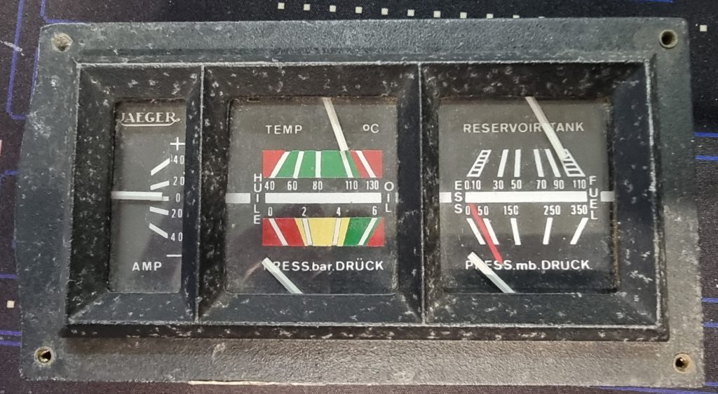
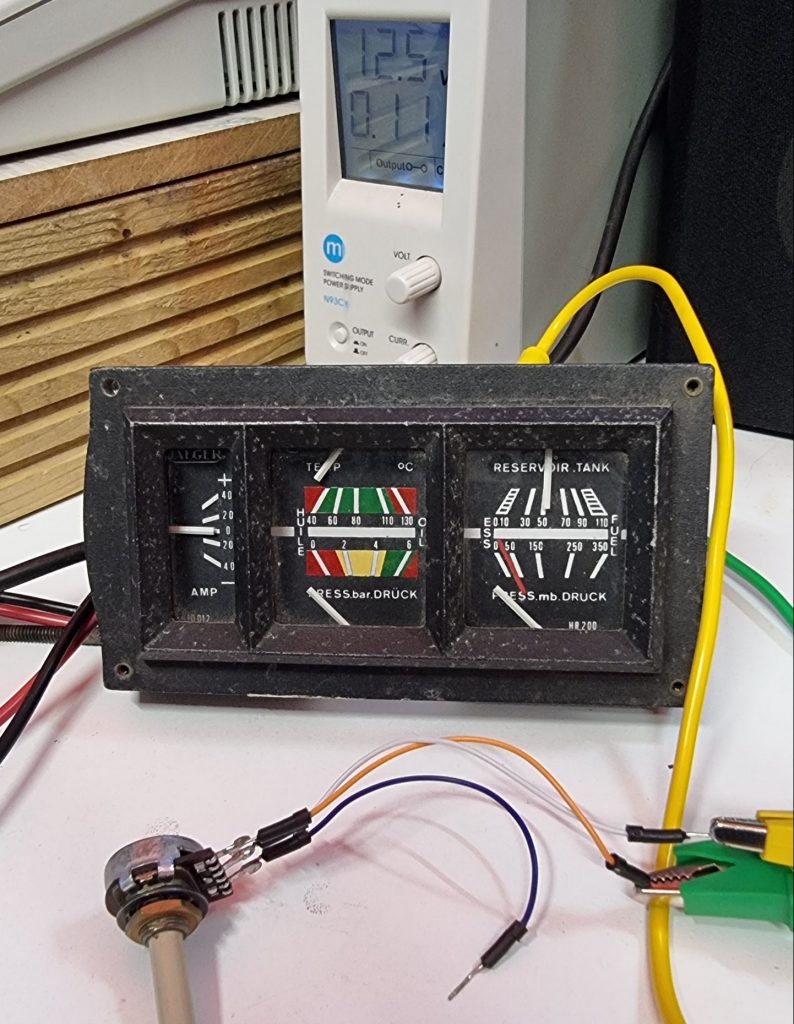
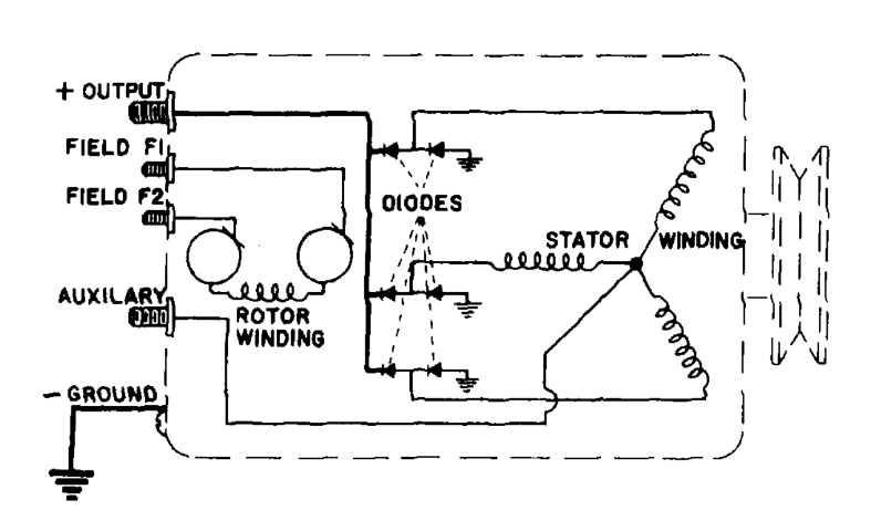
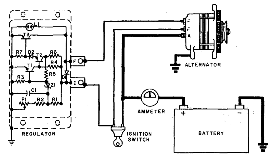
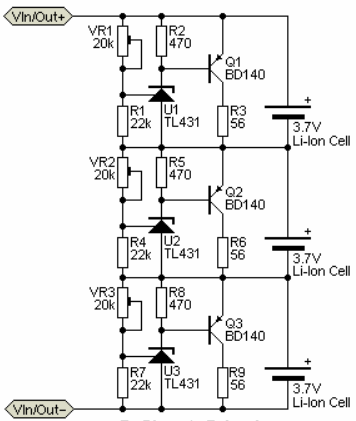
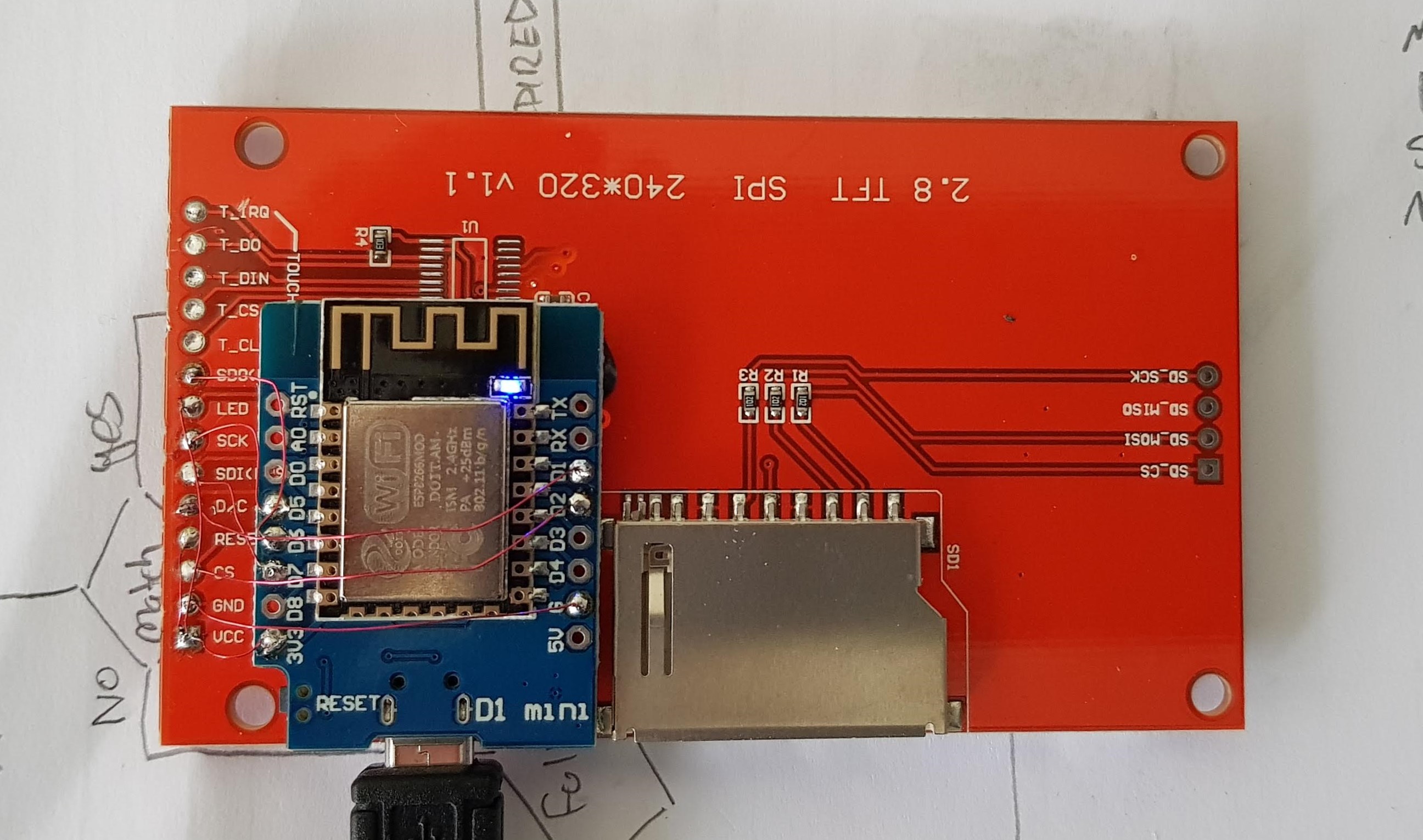
Fig 2
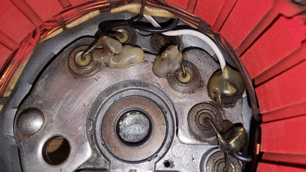
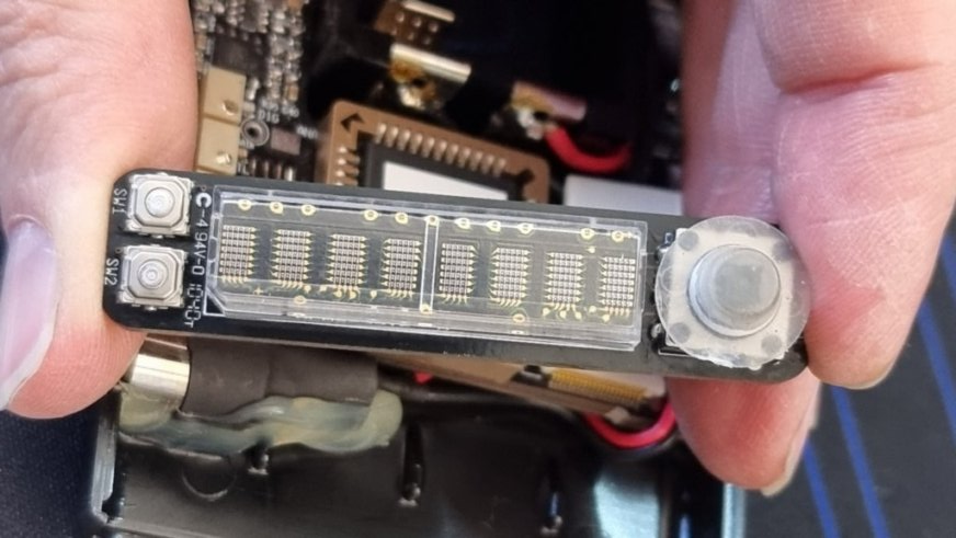
As soon as it arrived I checked to see if it was the same unit as in the actual aircraft and it is. There will never be another come up for sale, I can’t believe my luck. Obviously we should hook this up to 12V and see if it works. Its clearly not mass produced and you can see that the coloured bands are hand-painted. But its survived 50 years and for gauges in aircraft, which are notoriously unreliable this is amazing. The serial number between this one and mine is 13. We can guess that this any my aircraft were manufactured pretty closely together. I think it came from G-BICS which would be serial 104 approx. 50 later than mine.
How do these gauges work?
These are called “balanced magnetic indicators”. They are found in cars from all of the 20th Century and most aircraft such as Piper, Cessna, Robin etc.
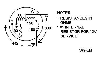
The three Coils are arranged in two Branches, where Coil III in Branch 1 and and Coil II are oriented at a right angle to Coil I of Branch 2. Because of the differing orientation of the Coils, the effective magnetic fields of the two branches are in opposing directions and combine to give a resultant field which has a quotient relationship between the two fields. In other words: it works by creating two magnetic fields that oppose each other, and the gauge shows the difference. The idea is that as the system voltage changes the gauge should show a proportional reading over a range of voltages.
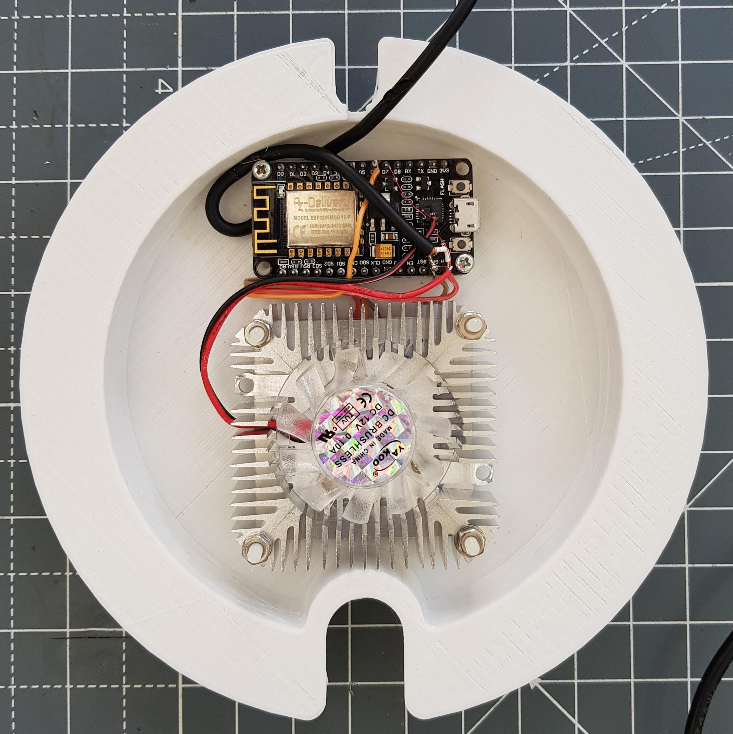
In Fig 2 above, I simulate the fuel sender with a variable resistor and use a system voltage of 12.5V. The fuel sender is a resistor to ground. In this way “senders” can earth through the vehicle chassis requiring only a signal wire. Wiring this up allows me to get any reading I like and fully exercise the meter.
This is where I realise how dodgy older gauges can be. I notice issues: its not linear, if you leave it on for 20 mins and let it soak (it generates a watt or so of heat) it drifts by 5% or so in the upward direction. Thats probably because the coil opposing the reading heats up, increasing its resistance and reducing the current and thus magnetic field. It changes by about 8% over 12V to 15V range for a fixed sender value. I always suspected that when the battery is low the fuel gauge reads a bit lower – it actually does. Finally, there is a bit of stiction in the movement; moving up to or down to the same value doesn’t always give you the same reading; but this doesn’t matter because the engine vibration sees to it that it doesn’t stick. For a 50 year old meter a value within 5% isn’t bad. I tested all the other gauges, they require different biases because the senders are all different but they all work work.
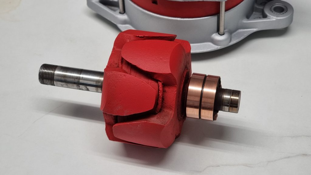
The ammeter is different. I thought it would be a current shunt with a moving coil meter but its not. Its a bar of brass (shunt) and the needle is a sprung loaded magnet. So the magnetic field, which is proportional to the current, tries to twist the needle against the spring which is linear – very simple. Of course if the current flows the other way, it twists the needle the other way and that allows the needle to show charge and discharge. The down side is that the needle bounces around with no damping and the readings are to be taken with a pinch of salt. Basically it tells you if you are charging or discharging. At +10A it was showing halfway to 20. at -10A it was showing closer to -15A but it doesn’t sit at zero either. You can adjust it, but best to leave it as its very fragile. High end gauges can be filled with mineral oil to add damping but it would only leak out – like it does on aviation compasses- which is a right pain.
Calibration
Next – does it agree with the actual aircraft meter? You cannot place the gauges in parallel, because the sender and the meter produce a potential divider, so putting two meters in parallel would halve its impedance and change the reading. Since my actual gauges may pack up at some point, its a good idea to see if they match now before that becomes an issue otherwise we’d be guessing. The answer is they agree within about 10%. So the fuel is reads 55 where as the plane reads 50, the others are in broad agreement. I didn’t check the ammeter because you can’t read either one sensibly – but you can check it on the bench and we already know its acceptable. We have used a calibrated thermocouple on the aircraft and the oil temp gauge is pretty close at 60C. For the fuel, when its showing about 60L and we brim the tank we get just under 60L of fuel in, and since the tank is 118L that shows its also reasonable.
If we ensure sufficiently high enough impedance input we can measure the voltages presented to the gauges at any indicated value we want and read off the voltage. This means we could build our own indicator which wouldn’t be susceptible to wear or temperature or voltage variation.
Measurements
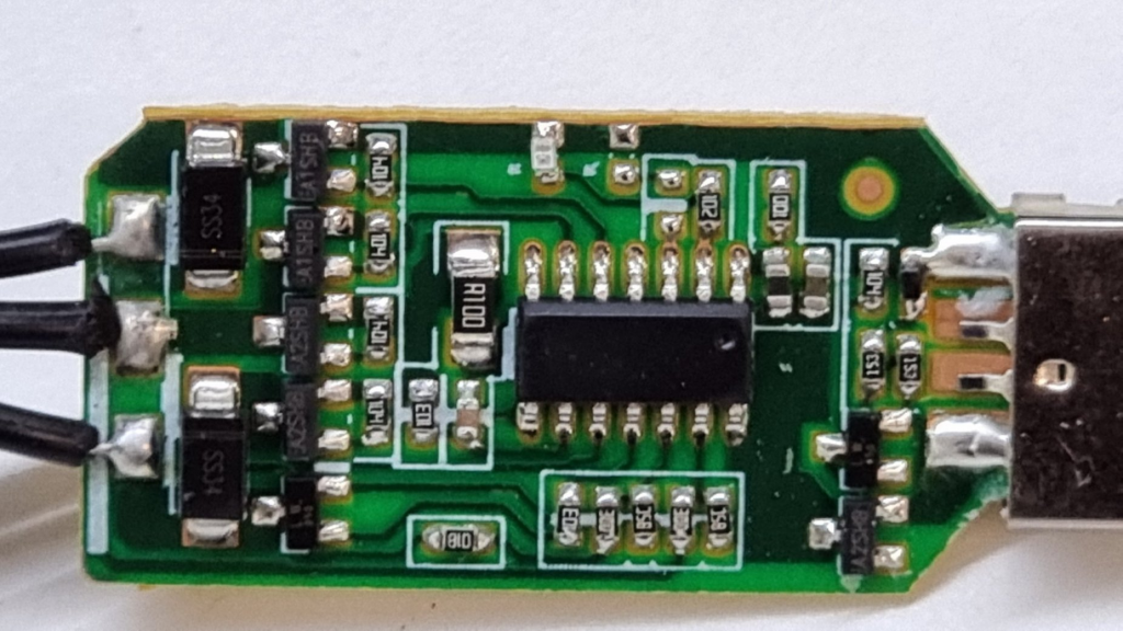
Since the gauges are only within a few percent there is no point investing in high precision instrumentation amplifiers and 10 bit resolution will be fine. I have boxes of esp32 controllers with ample analogue inputs available and whilst the esp32 isn’t known for having a super linear ADC (analogue to digital converter) its only poor at the extremes and rather than try to model its response and that of a filter, we might as well build the actual circuit and use the ADC values straight off. – I mean, we’re not going for mass production, so the values only need to be repeatable on this specific device.
The signal was fed in to a potential divider because the esp32 must be within 0 – 1V or 0 – 3.3V depending on the attenuation setting. The potential divider chosen is a potentiometer of 100k Ohms, thats because we do not want to load up the gauge because we’ll affect the reading – not just what we measure but the actual displayed gauge reading. Then after the potential divider a capacitor is added to ground which then forms a low-pass filter which will help reject noise and interference. This means our input impedance is about 100k and since the resistance of the gauges is a few hundred ohms, we are taking 1/1000th of the current the meter is which is 0.1%. 1% probably would have been fine, 10% wouldn’t be.
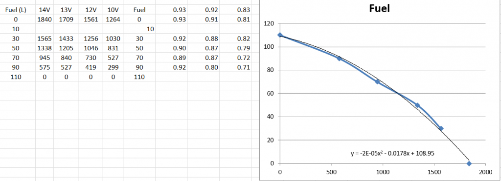
The reading is non-linear but remember that the sender is in parallel with half of the meter coils so that is of the form you’d expect. Using Excel we can get the formula for an approximation line form the actual values which results in over-reading at the higher fuel readings and under reads at the low end. That is definitely the way you want a Gauge!
Now, can we use those figures to build our fuel gauge? The answer is no. Because the actual voltage (ADC reading) changes with system voltage. The mechanical gauge compensates for this because the current flowing through the coil is proportional to system voltage. But we need to compensate for it.
So we pick a middle reading and observe it across a sensible voltage range.
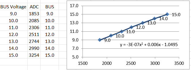
What we get is a linear relationship. That makes sense because basically the current in the meter scales with system voltage.
When plotting the values against various bus voltages we see that the readings are simply scaled and they cross the axis at zero.
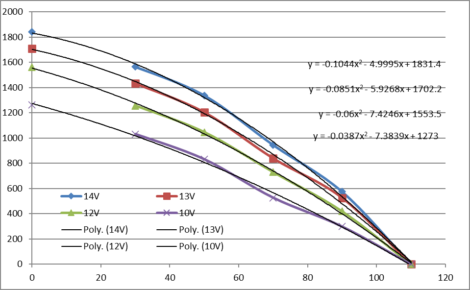
Another thing to think about is the geometry of the fuel tank. Ours is like half a barrel on its side, that means that the volume isn’t linearly related to depth, the level drops faster as the volume decreases. If you look at the gauge to see that the manufacturer has squeezed the higher readings closer together but also the way these coils work also has the inverse effect which helps with linearity.
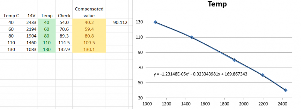
Here we can see the 14V values and then the transfer function. We then use the raw values through the inverse transfer function so cross-check our work and the values are reasonable, any deviation would be impossible to see on the actual gauge.