An engineer at my local Tesco store obviously needed to get a camera working but didn’t have the PoE power injector he needed. Was that going to stop him- not by the looks of it!
You have to have some random projects…
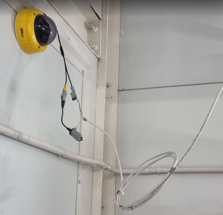
An engineer at my local Tesco store obviously needed to get a camera working but didn’t have the PoE power injector he needed. Was that going to stop him- not by the looks of it!