I had forgotten to post updates to the project. Progress was extremely slow because of family etc.
I really liked the Pilotaware system having known people personally to die in GA mid-air collisions. If you have a certified aircraft, you cannot change anything and it must be regarded as carry on. However, what you don’t want is a mass of cables and obstructed views.
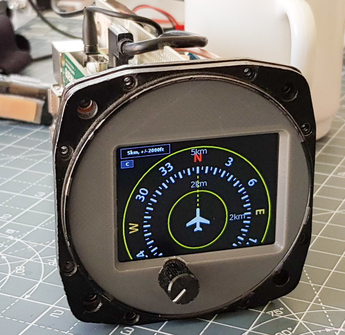
The Pilotaware radar view is awesome as it is, but its a fiddle to connect to it on your phone and a distraction you don’t need. My idea was to create a purpose built display. I searched on eBay until I found a 1950’s ADF that would form a chassis that I could use. It was plenty big enough and had standard connectors already on it- someone already did all the hard work!
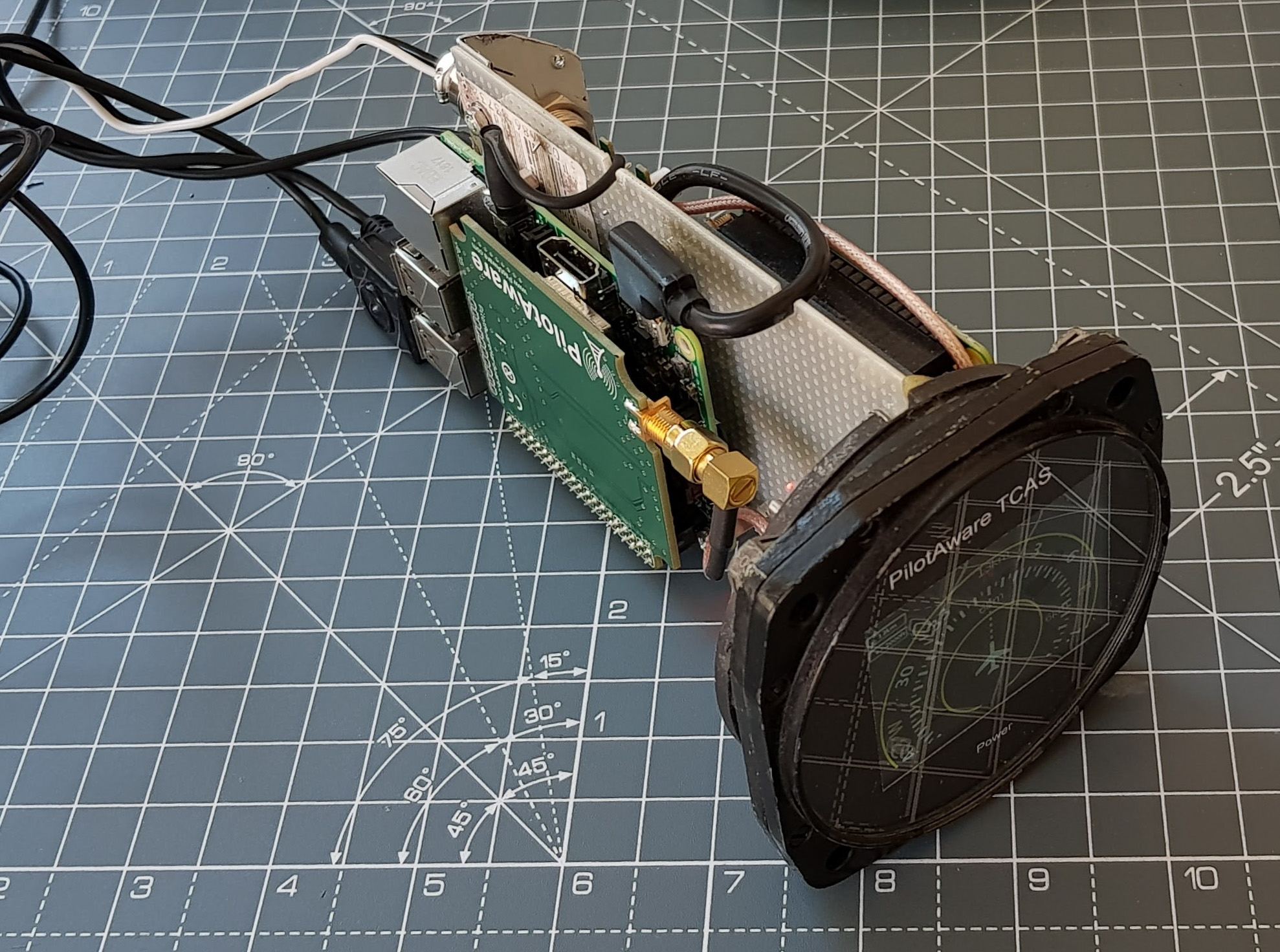
Then I realised that I’d be creating a system ideal to support the actual Pi. So I stuck the Pilotaware Pi in the back. One box, one set of connections.
Internally it is based on the following
- Anker 5V 3A charger – recommended by Pilotaware as its very low noise and seems to cause the least issues. This is happy with anything between about 7V and 28V and provides a rock-solid 5.1V output.
- A Pilotaware radio module, attached to a Raspberry Pi 2 Model B (that’s how it came)
- Pi Zero with Bluetooth and Wifi – amazing that this is only a tenner.
- Adafruit 2455 Pi TFT 2.4 Inch touch display – I very carefully cut the touch overlay off because it was too reflective and not required. Getting the display to work on the Pi Zero was a bit of a pig.
- Vero Strip board – some mil-spec stock I acquired ages ago.
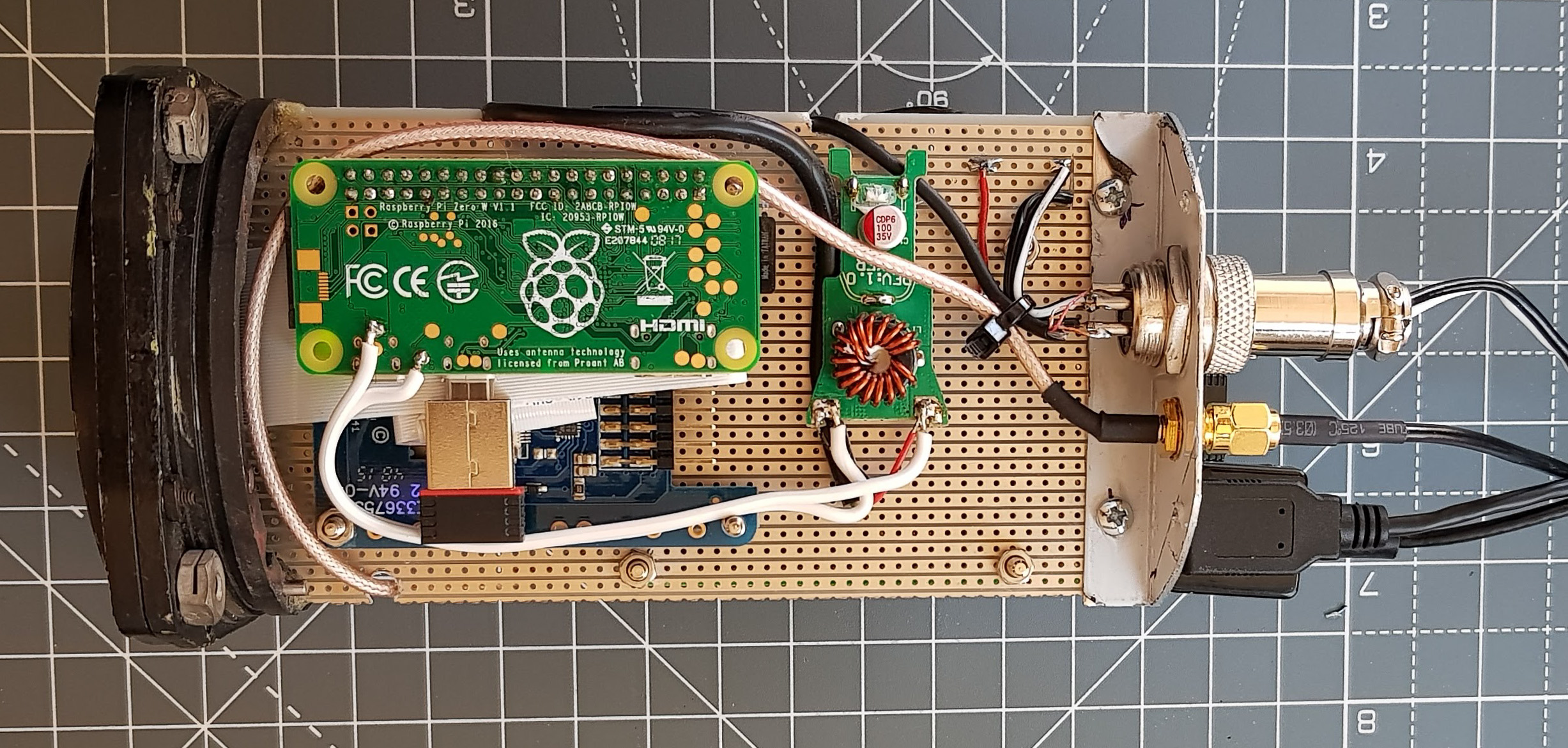
Pi Zero 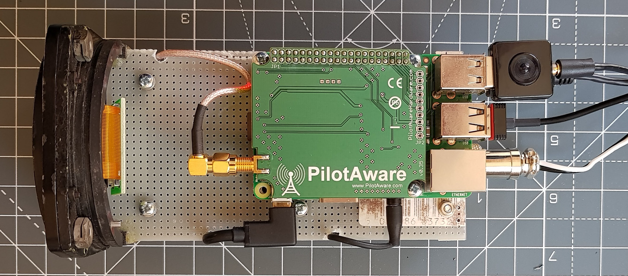
The Pilotaware unit 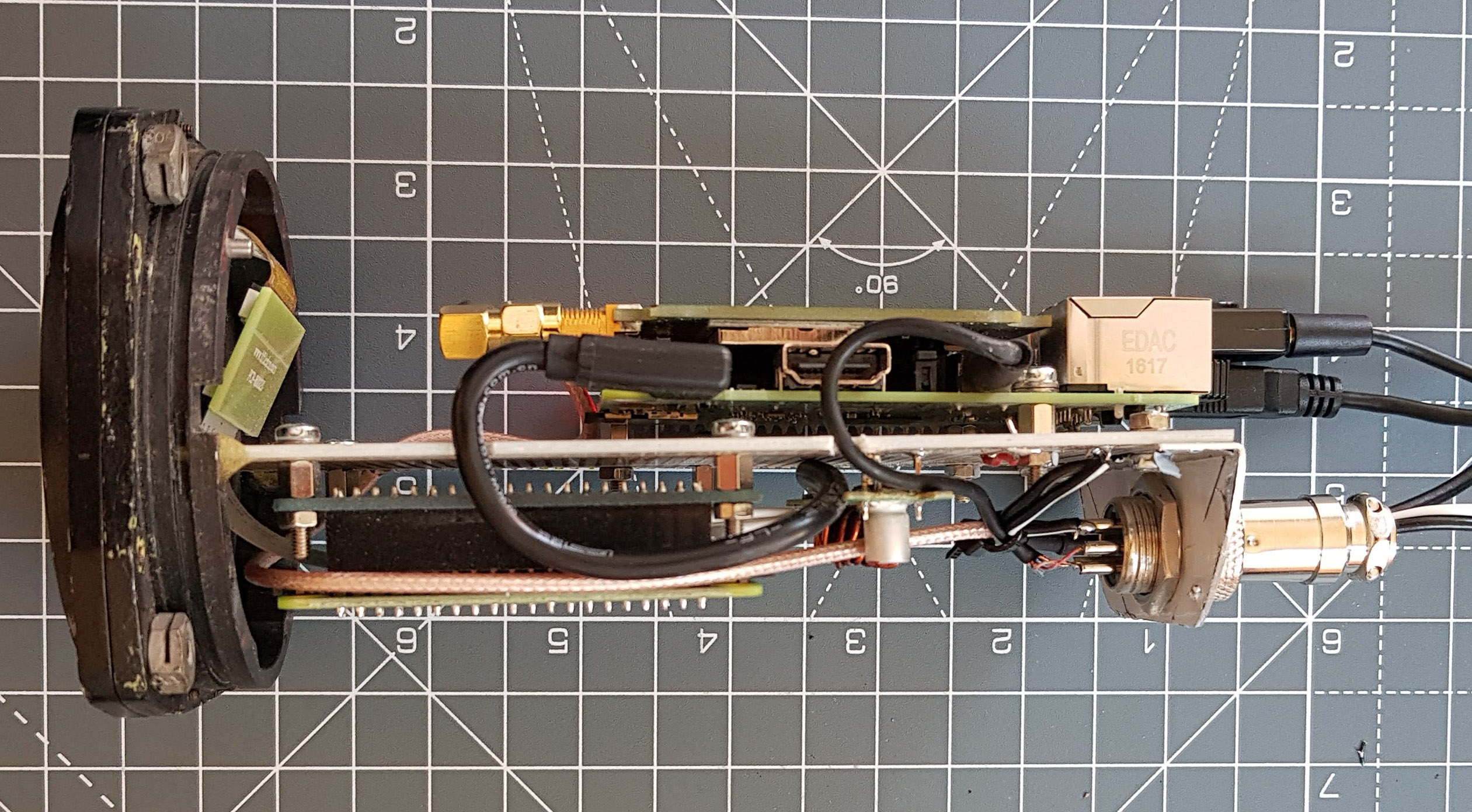
see all the bits 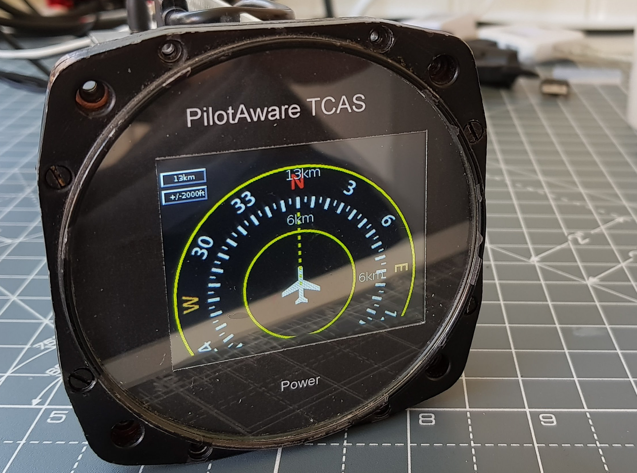
Early bench prototype – The LCD bezel is just printed on a laser printer
Software
Setting up the Pi Zero was a bit of a fiddle. I wrote a script to keep trying to connect to the Pilotaware system. Next, it starts the x windows environment and opens a windowless browser to the radar page. There is a script that checks that all is well and if it does loose connection it will sort itself out.
Hacking the Pilotaware
The radar app isn’t quite right. The lines are too thin and on a low resolution the screen its too difficult to see – so I needed to alter it. You cannot get access to the Pilotware system because they don’t give you the password. However that doesn’t offer much of a challenge. In the end I mounted the card under windows using some Paragon software.
I altered the CSS significantly and changed the javascript that draws on screen, to make everything using fully saturated colours and 3 pixel width line to make it really easy to see. I drew my own Compass Rose which is a PNG file. In the end it looks like a proper glass cockpit design. I wanted to keep mods to a minimum otherwise updating it is a pain. In the end I created a Radar2 folder such that updating the system leaves my hacked version intact. It sounds like I know what I’m doing with this; I didn’t it took ages – this project was on an off over 18 months. I created a debug environment and could locally test it using chrome with mobile device screen set up.
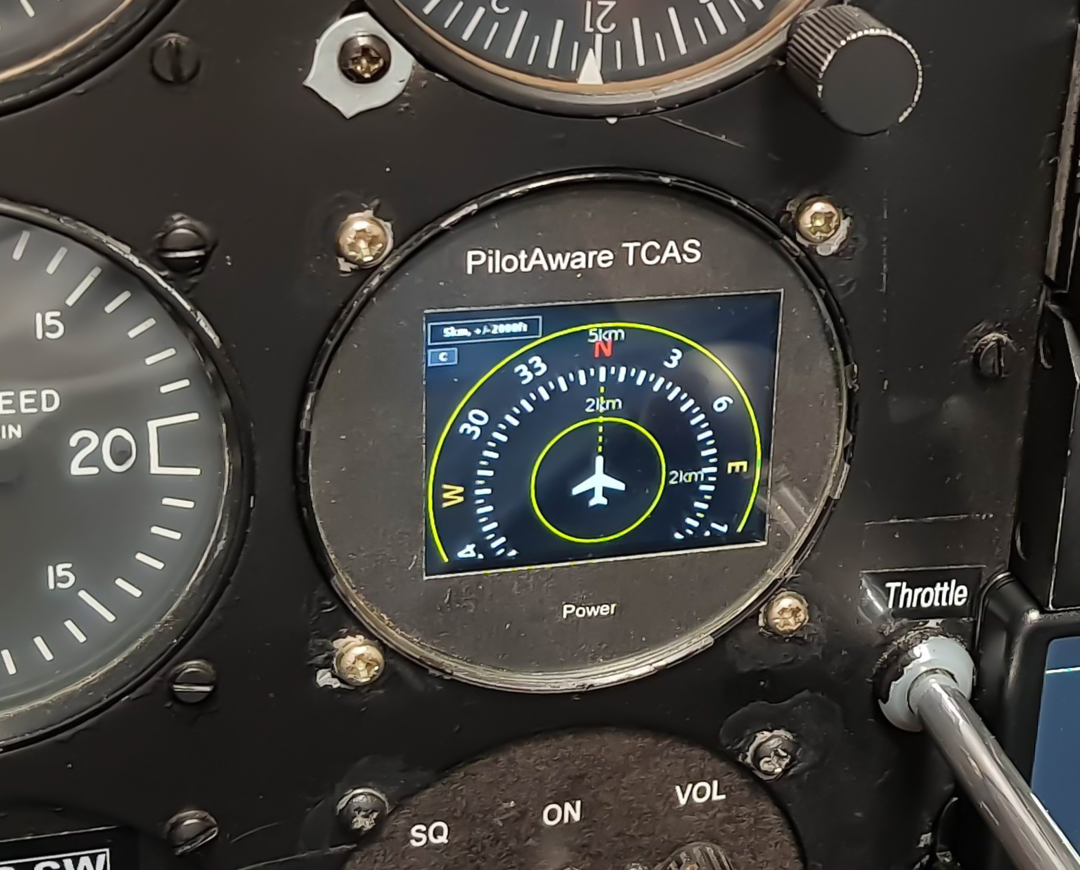
I wanted to see what it would look like on a real panel, from the pilots seat its lucky that this is a good angle for this screen.
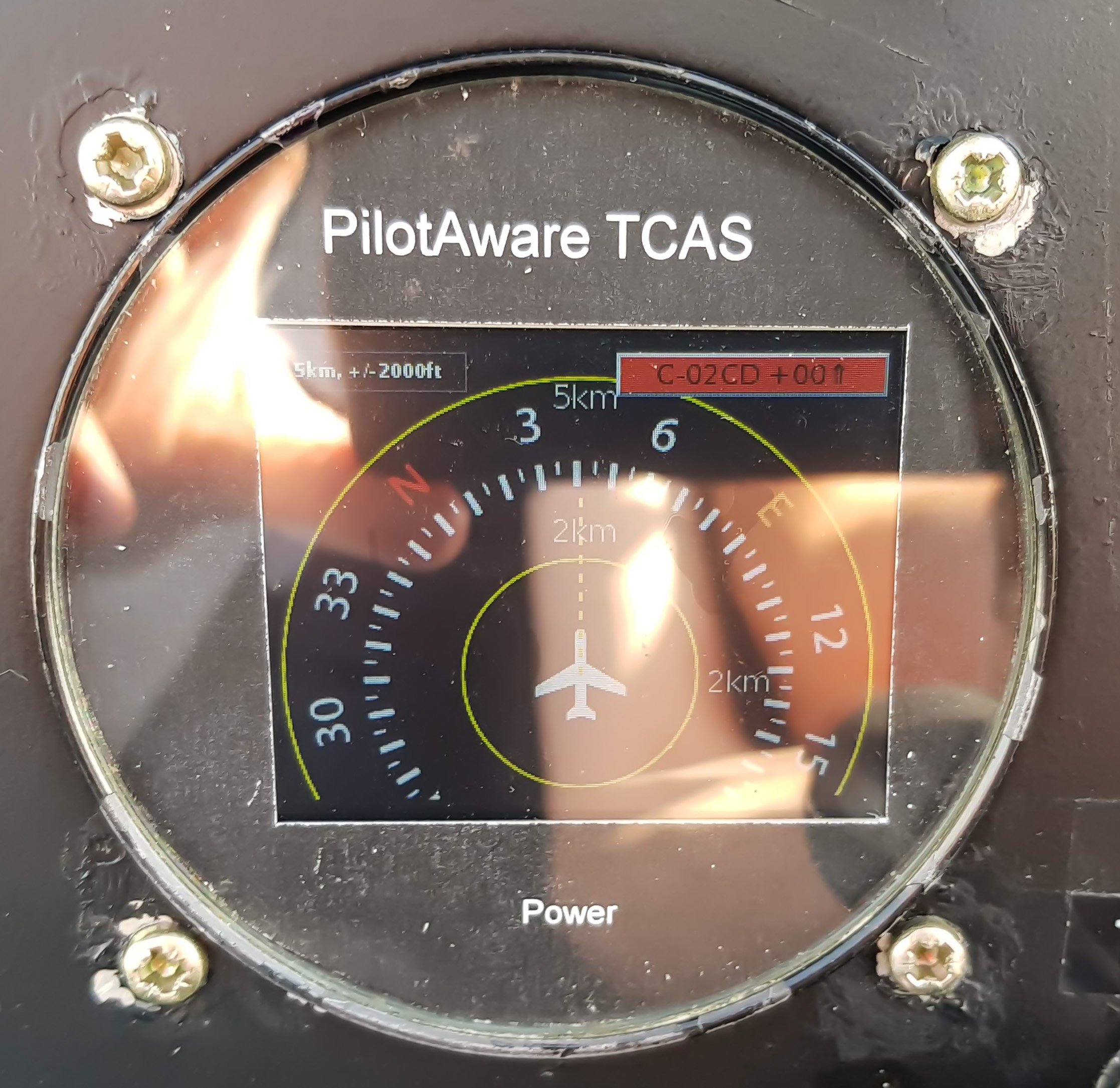
Unfortunately, in sun light the screen reflections are a problem. I looked at anti-glare film and bonding the display to the screen like a smartphone but these are messy solutions.
What would be better is no glass. I 3D printed a prototype bezel. Shown here was an early prototype. The volume / power knob can now be added as there is no glass to worry about. I also added an LM386 audio amplifier connected to the Pi so you can hear the traffic alerts. Volume / Mute was a must. I scrapped the text and mention of TCAS because it isn’t TCAS, its a traffic aid.
Most connections are made remotely over a 2m cable with a Tesco USB hub. For some reason all sorts of expensive micro-hubs wouldn’t work but a 4 year old one from Tesco’s works perfectly. This allows easy placement of GPS and ADSB receiver at the back of the cockpit out of the way rather than trailing cables all over the place possibly jamming the controls!
I’ve worked hard to ensure that it produces as little radio frequency interference as possible. I have the old non 8khz navcom to play with on the bench and I also have a scope that shows the radio frequencies and strength being emitted so they can be addressed. The power inlet is RF filtered and the case forms a Faraday cage. Additional shielding was still necessary and grounding was a bit of a dark art. In the real aircraft, I realised I probably didn’t need to worry as the existing electrical noise was 3 orders of magnitude higher. There is a lot of electrical noise from the strobe and the alternator, its a wonder any radio navigation equipment works at all.
Final Thoughts
I think this project worked out quite nicely and I learned a lot doing it. It gives you an appreciation for the complexity and radio compatibility issues you can have with airborne systems. My end result with its black panel doesn’t look like its homemade and the performance is remarkable and I tested in the car at the airfield.
Unfortunately, you can’t fix something like this into a certified aircraft – though I’m sure many would. You can place it on the top of the dash although I hat anything obstructing the view – a non-moving dot hiding behind it is exactly what traffic on a collision course looks like.