As an aviator its important to know what the weather is doing and in my case whether there is an point tuning up to the airfield.
I had been toying with the idea of making a retro LED clock for some time, but as I now have to use an ESP8266 connected device for everything because its cheap and east to use, I thought I could add value by displaying the current METAR. A METAR is an aviation text encoded weather observation that really belongs 100 years in the past, but is still useful. It tells us what the wind is doing, the pressure, cloud and visibility. These are all available online in JSON requests or via many free API’s. So all we need to do is make a web request.
The ESP8266 does not have a real time clock, but it is able to sync with NTP (Network Time Protocol) and keep time that way. So all we really need is the ESP8266 and the LED display.
Two 4 panel LED displays is too large for my 3D printer so its made it two halves. Simple affair, there is no back but it includes screw hangars and a notch for USB entry.To join the two LED panels, I used 5 wire links between them.CDS light cell / resistor tacked on to the board allows sensing of ambient light levels. Other than that its all driven directly from the ESP8266, the USB powers everything.
ArduinoOTA – allows for it to be updatable over the air, essential when its screwed to the wall.
Adafruit GFX Library – required for the LED panel.
MegunoLink – used to filter the light sensor data to stop the brightness hunting.
ArduinoJson@5.13.4 – specific version required to parse the JSON web request for the METAR data.
WifiManager – to create a hotspot to allow the device to be configured.
Max72xxPanel – the shift register driver for the matrix panel.
Refinements
I found that the string class, although very powerful, can lead to heap fragmentation on the ESP8266. The forums are not terribly helpful basically saying that people should learn to use char arrays and pointers instead and stop being lazy. Whilst that may be true especially on a tiny process with a few kb of RAM its not helpful when leveraging 3rd party libraries, particularly the JSON class – you could do this manually but its unwieldy.
The solution I went for is to restart the ESP every 24 hours instead to clear up the memory. The LED display will just retain whatever it was showing whilst the restart fires, and it only takes a few seconds. I may revisit this and refine it a bit later, but for now its perfectly workable.
Clones
As it happens by word of mouth I have made quite a few of these. Its ironic that the most expensive part is a nice USB cable! There’s one at Flightpath flying school at Wolverhampton Halfpenny Green.
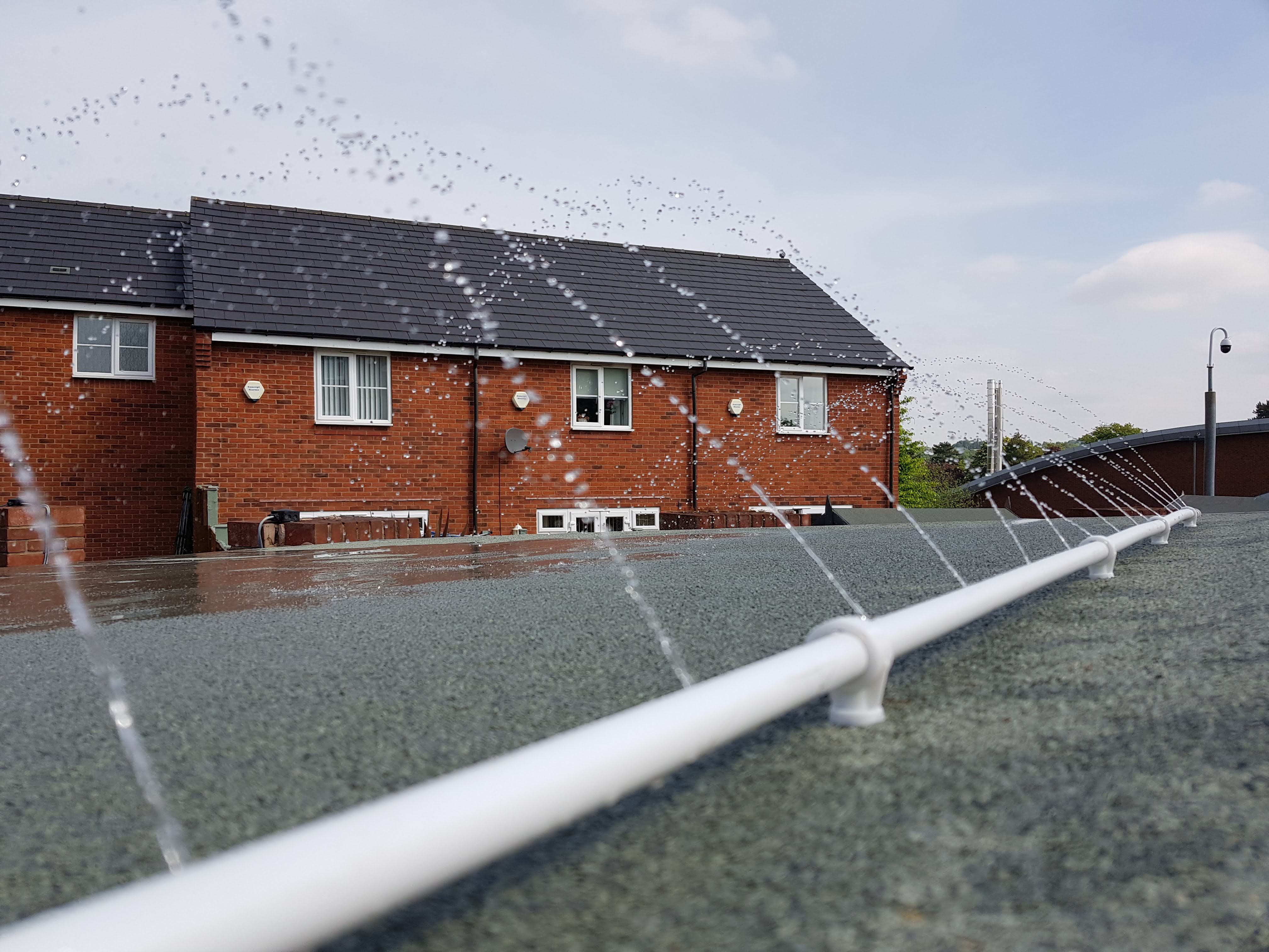
This year, we’ve all been working from home. I’m very lucky to have a man shed to work in. In very hot weather though it can become far too hot to work in. The roof is dark and in direct sunlight on a hot day we are looking at 40C.
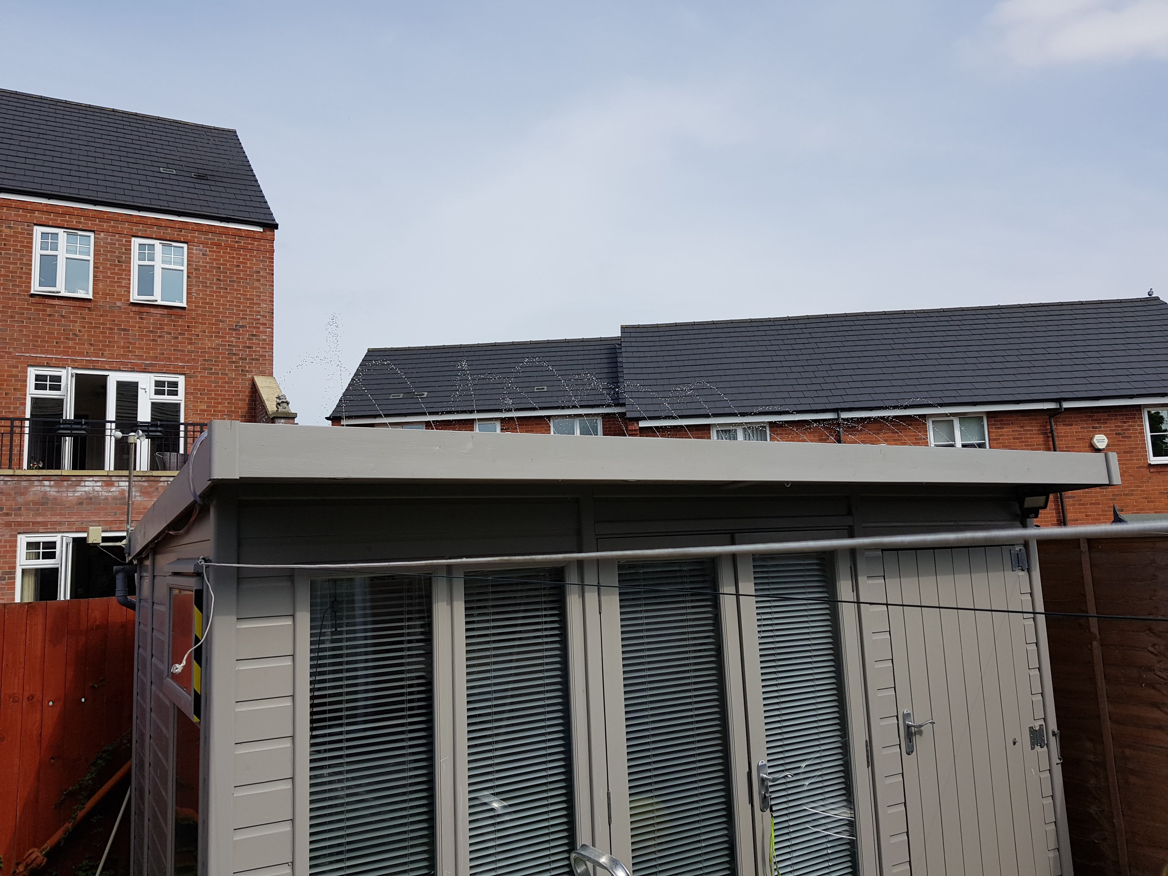
The shed has a gutter and a water butt, so I decided to create a water cooling circuit with some PVC pipe arranged as a spray bar. I used a PWM motor speed control circuit and a 12V bilge pump from eBay.
On a hot day the roof would reach 66C. With the water cooling it would bring that down to 28C. Its not so much the water cooling the roof as the evaporation of that water, so I don’t need to spray a lot of water, just keep it damp. The specific latent heat of evaporation of water is staggering so the cooling effect is very real and quite dramatic. On the hottest days, the roof evaporated 25l of water which is many megawatt hours of energy, powered directly from the sun – that otherwise would have cooked me.
Refinements
The evaporation was so effective that I had to add a float switch to prevent the pump running dry and I had to top up the water every other day unless it rained.
I added an irrigation inline filter to stop debris clogging the jets. Again, where else, a fiver on eBay.
A battery management system needed to be added and this proved to be tricky. For convenience we want a rechargeable battery and, like any gadget, to be able to charge it from USB. The unit draws 170mA and I opted for a 1000 mAh lithium battery which includes battery protection from overcharge, short-circuit etc. This should see up to 5 or more hours use. I used a charge management chip and programmed the charge current to 300mA. This conservative charge rate means a very safe 3.5hr charge time and doesn’t demand too much from the battery.
Case Design
Prototyping The Case
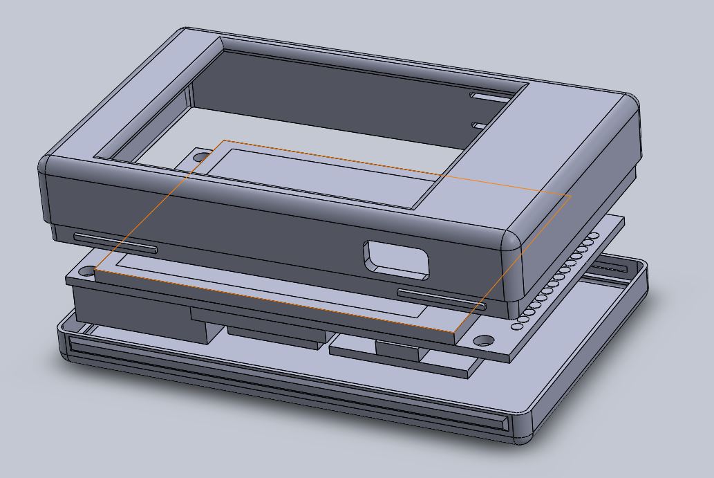
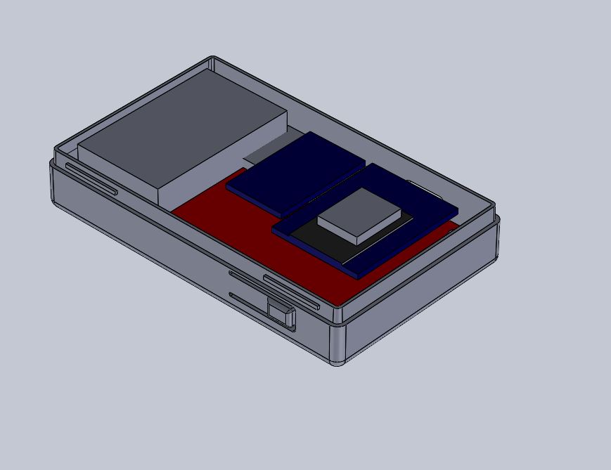
I wanted to make a device that was as small and lightweight as possible. After modelling the display PCB, all the other parts were modelled as accurately as possible. Finally we know the minimum size the case can be. Originally I designed it with screws, but then I realised I was still thinking like it would be made from milled metal – now I can 3D print a case I can make it snap together. Note the two tabs on the top part which snap in to the bottom part. The thinnest shell I was comfortable with was 2mm and this makes the case a feather weight and yet still surprisingly rigid.
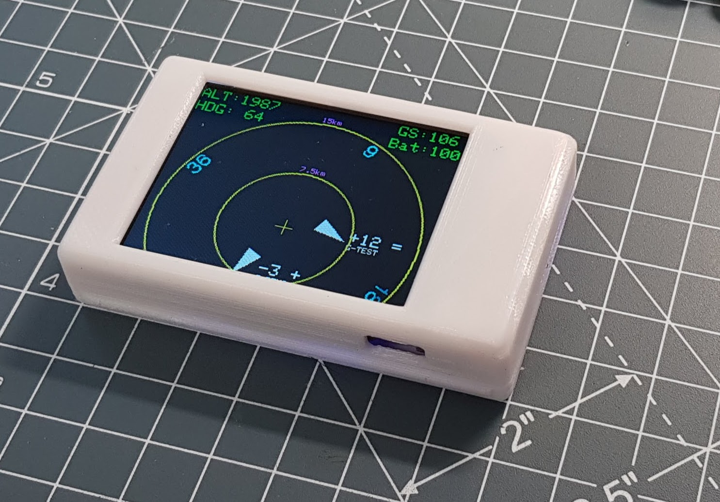
For the switch I tried a few different things and again I was thinking along the wrong lines. Plastic allows you to make flexible parts. The switch can be made out of the body in one piece, which is quick cheap and simple. Just cut a slot so it can move. I added a raised area to make it easy to find and since the print direction is left to right, its optimal for the 3D print. It worked really well and I’ll definitely use this technique in future. I wanted a black case, but have lots of white PLA that I needed to use up so the prototype cases were white.
Prototype Case
The software was updated to hook up the ADC input to monitor battery voltage. A housekeeping task runs once per second and this monitors the voltage and displays approx capacity rounded to the nearest 25% – for simplicity.
In the previous project, we saw a traffic display involved a far bit of hacking of the Pilotware unit. The downside of this is that it makes it difficult to keep the Pilotaware unit up to date.
The Pilotaware unit provides traffic information via a Wifi hotspot. The system provides an interface on port 2000 which provides FLARM and NMEA GPS information.
What we need is something lightweight, cheap with wifi and a display. Until recently this would have been an expensive development, but today we have the internet of things. Esspressif systems have made this extremely easy with a system of a chip, which includes WiFi, can easily be programmed in C++ using arduino compatible libraries …..and all for the price of a McDonalds! It should be possible to create a unit about the size a fag packet that you can stick the dashboard for very low cost.
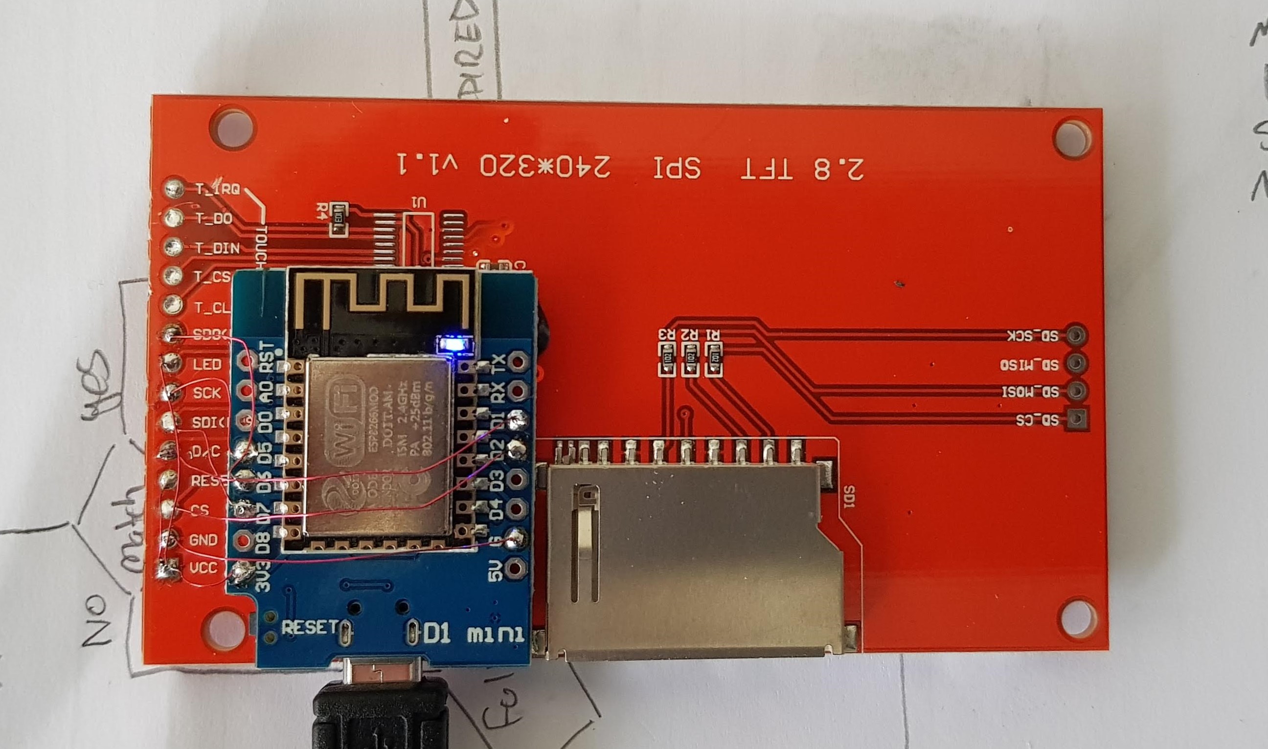
A complete computer (esp8266) for £5 and a £10 TFT colour display.
All that is required is to connect the esp8266 serial peripheral interface to the display. In this case I used a wimo d1 mini board.
Next we need to connect to the PAW which is only a couple of lines of code, then connect to port 2000 and handle the data stream. Once that’s done we install some SPI display libraries and we can draw whatever we want on the screen.
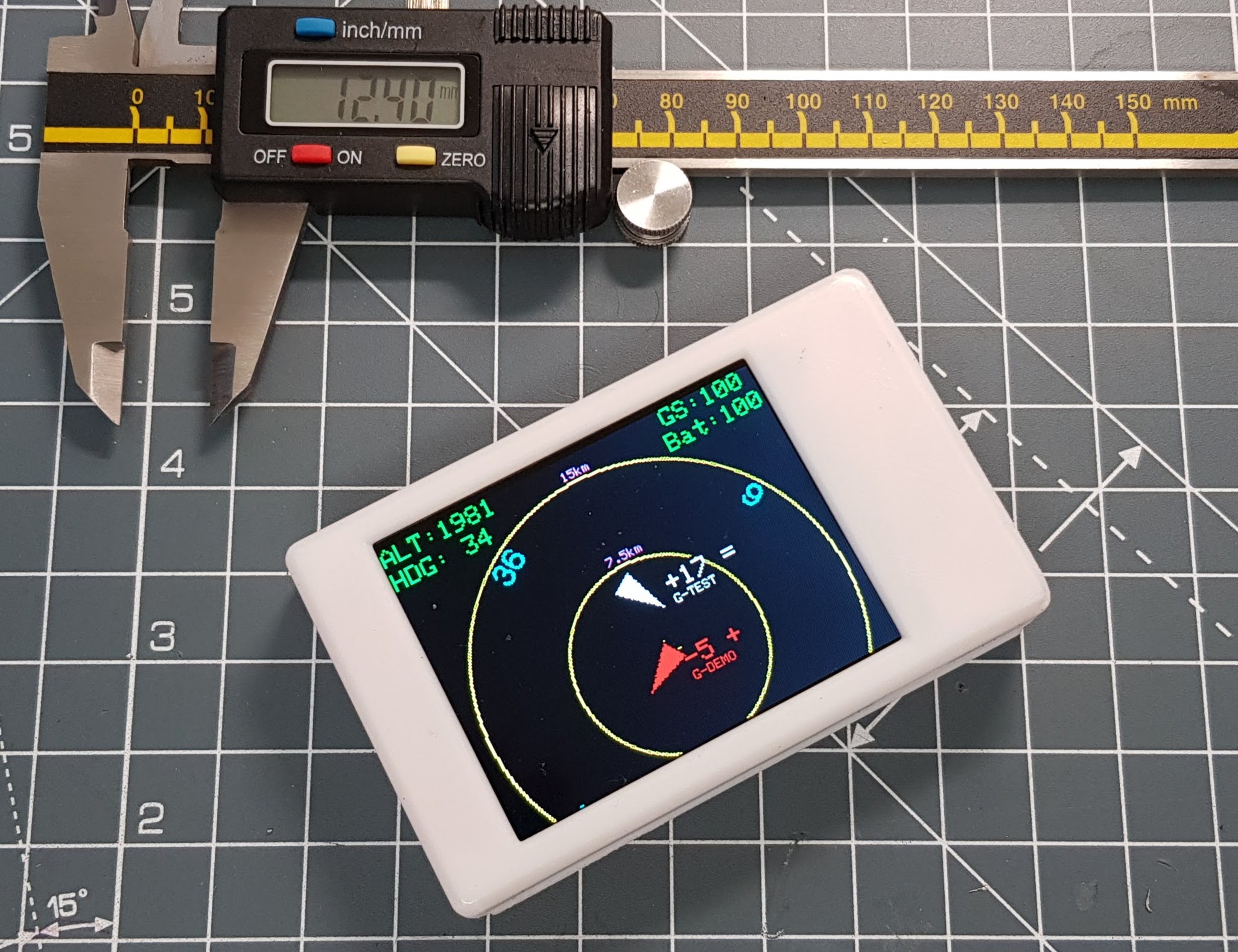
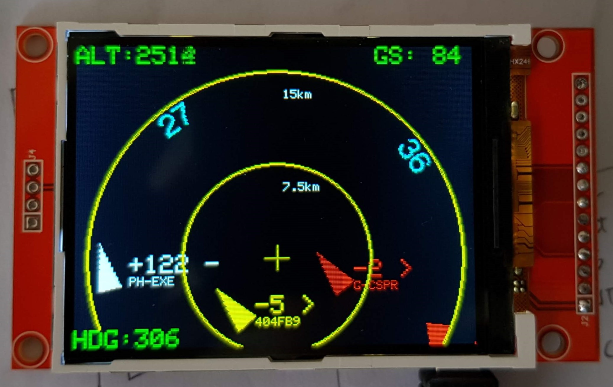
Space invaders
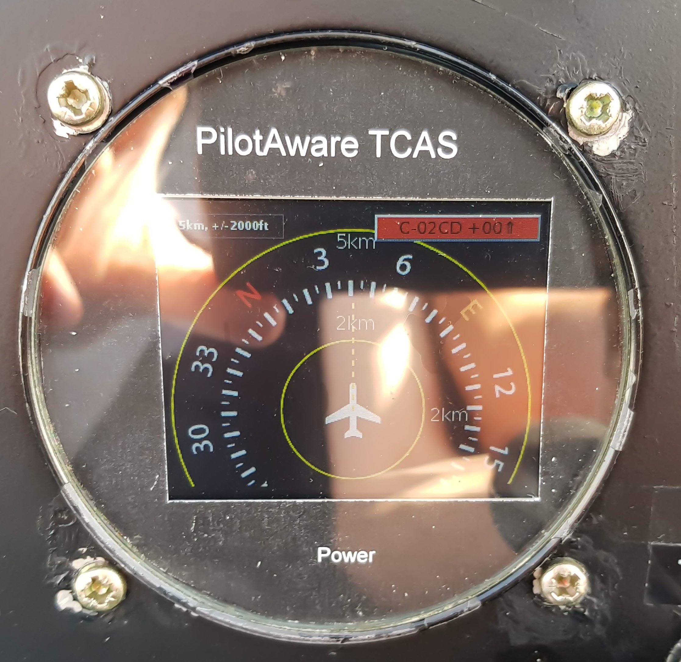
I chose to depart from the TCAS display symbols because I’m not used to them and I found a ‘spaceship’ pointing towards me far easier to interpret than squares moving sideways. Other than that the large number indicates the level and I can display the reg or whatever with it.
Next Steps
3D printed case
USB Rechargeable lithium battery – gives about 7 hours of use from a 1 hour charge.
I had forgotten to post updates to the project. Progress was extremely slow because of family etc.
I really liked the Pilotaware system having known people personally to die in GA mid-air collisions. If you have a certified aircraft, you cannot change anything and it must be regarded as carry on. However, what you don’t want is a mass of cables and obstructed views.
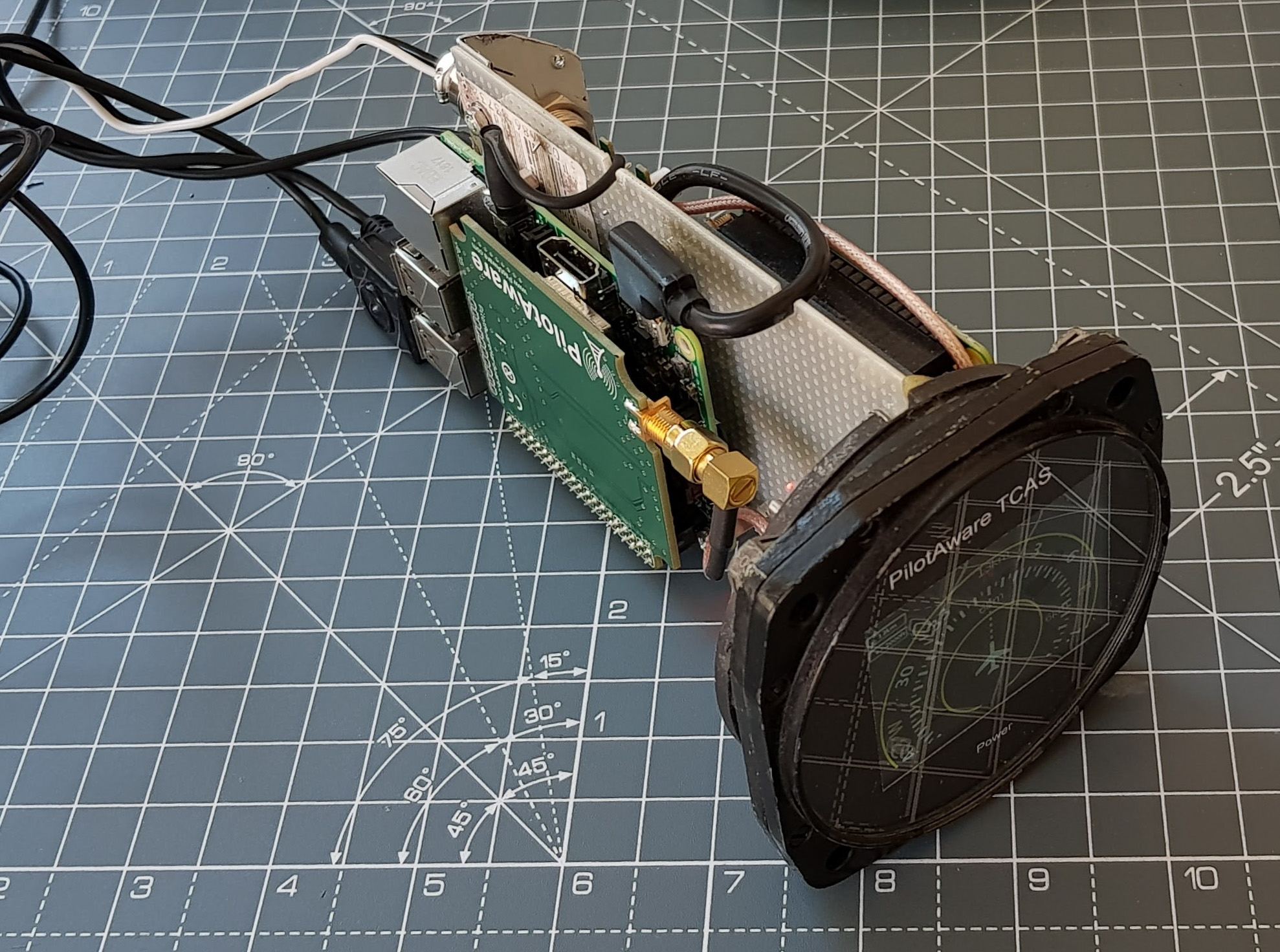
The Pilotaware radar view is awesome as it is, but its a fiddle to connect to it on your phone and a distraction you don’t need. My idea was to create a purpose built display. I searched on eBay until I found a 1950’s ADF that would form a chassis that I could use. It was plenty big enough and had standard connectors already on it- someone already did all the hard work!
Then I realised that I’d be creating a system ideal to support the actual Pi. So I stuck the Pilotaware Pi in the back. One box, one set of connections.
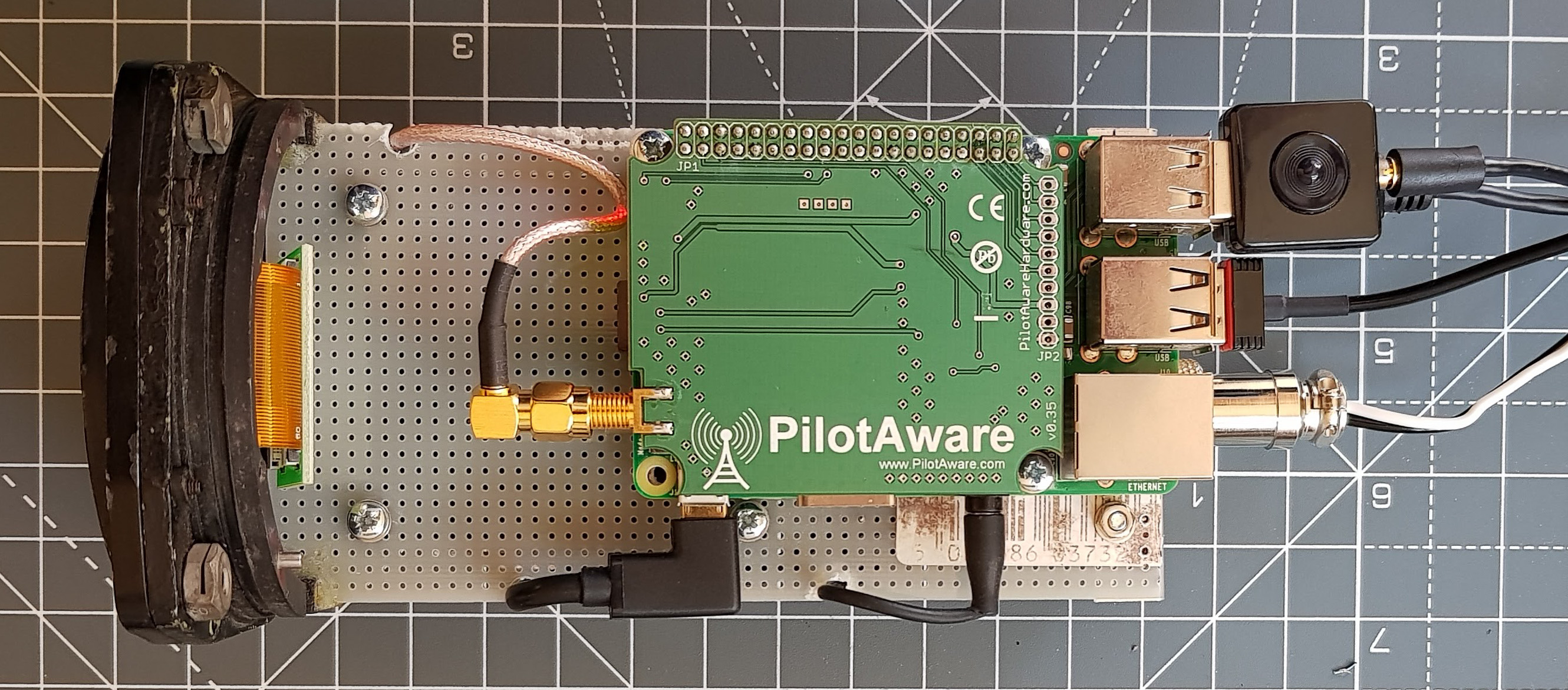
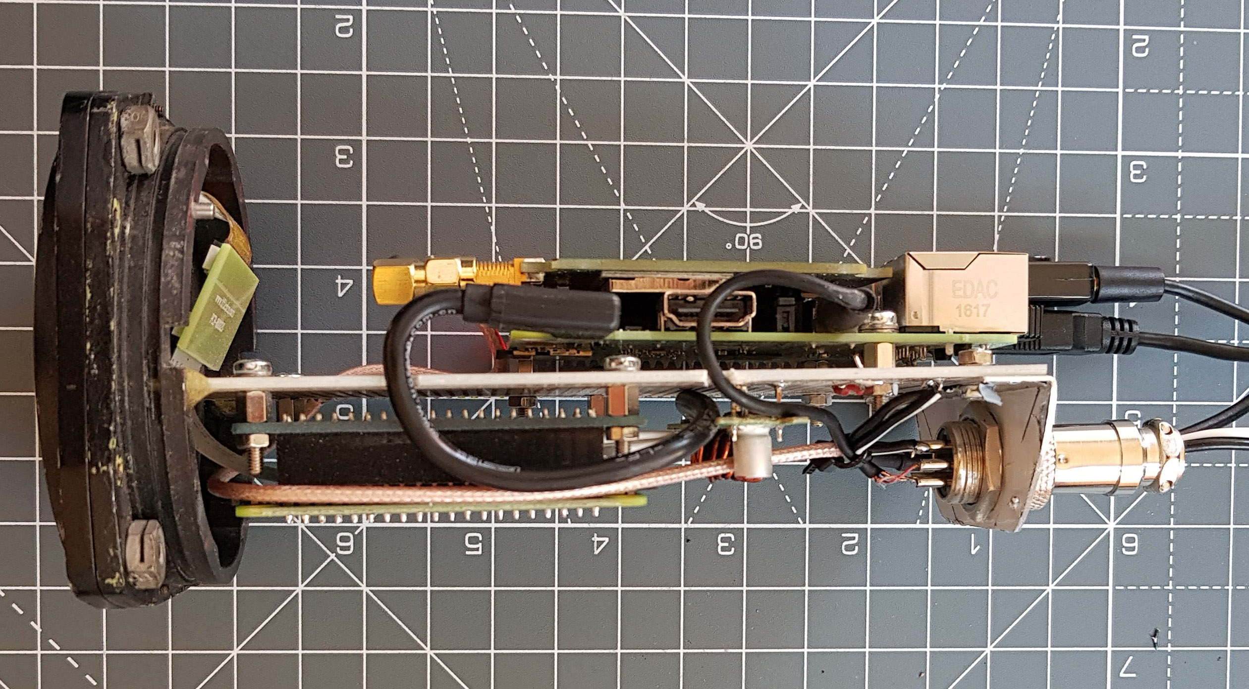
System Internals
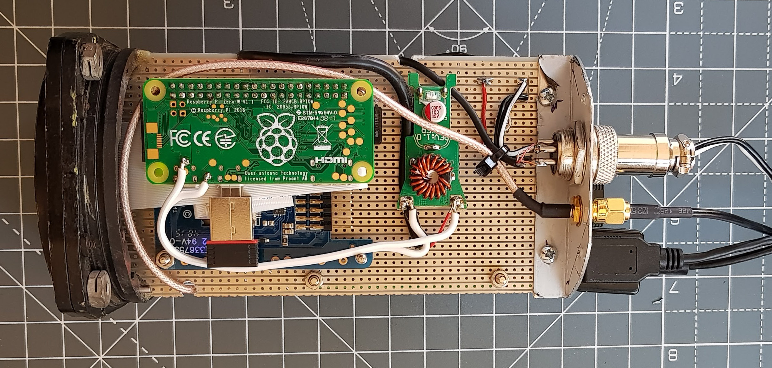
Internally it is based on the following
Anker 5V 3A charger – recommended by Pilotaware as its very low noise and seems to cause the least issues. This is happy with anything between about 7V and 28V and provides a rock-solid 5.1V output.
A Pilotaware radio module, attached to a Raspberry Pi 2 Model B (that’s how it came)
Pi Zero with Bluetooth and Wifi – amazing that this is only a tenner.
Adafruit 2455 Pi TFT 2.4 Inch touch display – I very carefully cut the touch overlay off because it was too reflective and not required. Getting the display to work on the Pi Zero was a bit of a pig.
Vero Strip board – some mil-spec stock I acquired ages ago.
Pi Zero
The Pilotaware unit
see all the bits
Early bench prototype – The LCD bezel is just printed on a laser printer
Software
Setting up the Pi Zero was a bit of a fiddle. I wrote a script to keep trying to connect to the Pilotaware system. Next, it starts the x windows environment and opens a windowless browser to the radar page. There is a script that checks that all is well and if it does loose connection it will sort itself out.
Hacking the Pilotaware
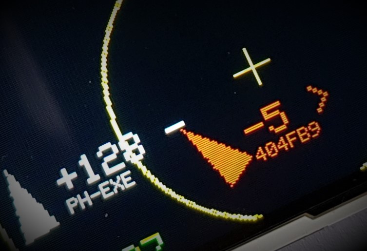
The radar app isn’t quite right. The lines are too thin and on a low resolution the screen its too difficult to see – so I needed to alter it. You cannot get access to the Pilotware system because they don’t give you the password. However that doesn’t offer much of a challenge. In the end I mounted the card under windows using some Paragon software.
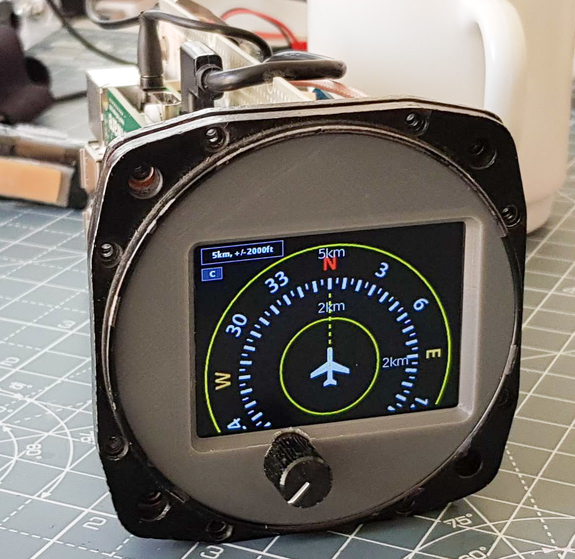
I altered the CSS significantly and changed the javascript that draws on screen, to make everything using fully saturated colours and 3 pixel width line to make it really easy to see. I drew my own Compass Rose which is a PNG file. In the end it looks like a proper glass cockpit design. I wanted to keep mods to a minimum otherwise updating it is a pain. In the end I created a Radar2 folder such that updating the system leaves my hacked version intact. It sounds like I know what I’m doing with this; I didn’t it took ages – this project was on an off over 18 months. I created a debug environment and could locally test it using chrome with mobile device screen set up.
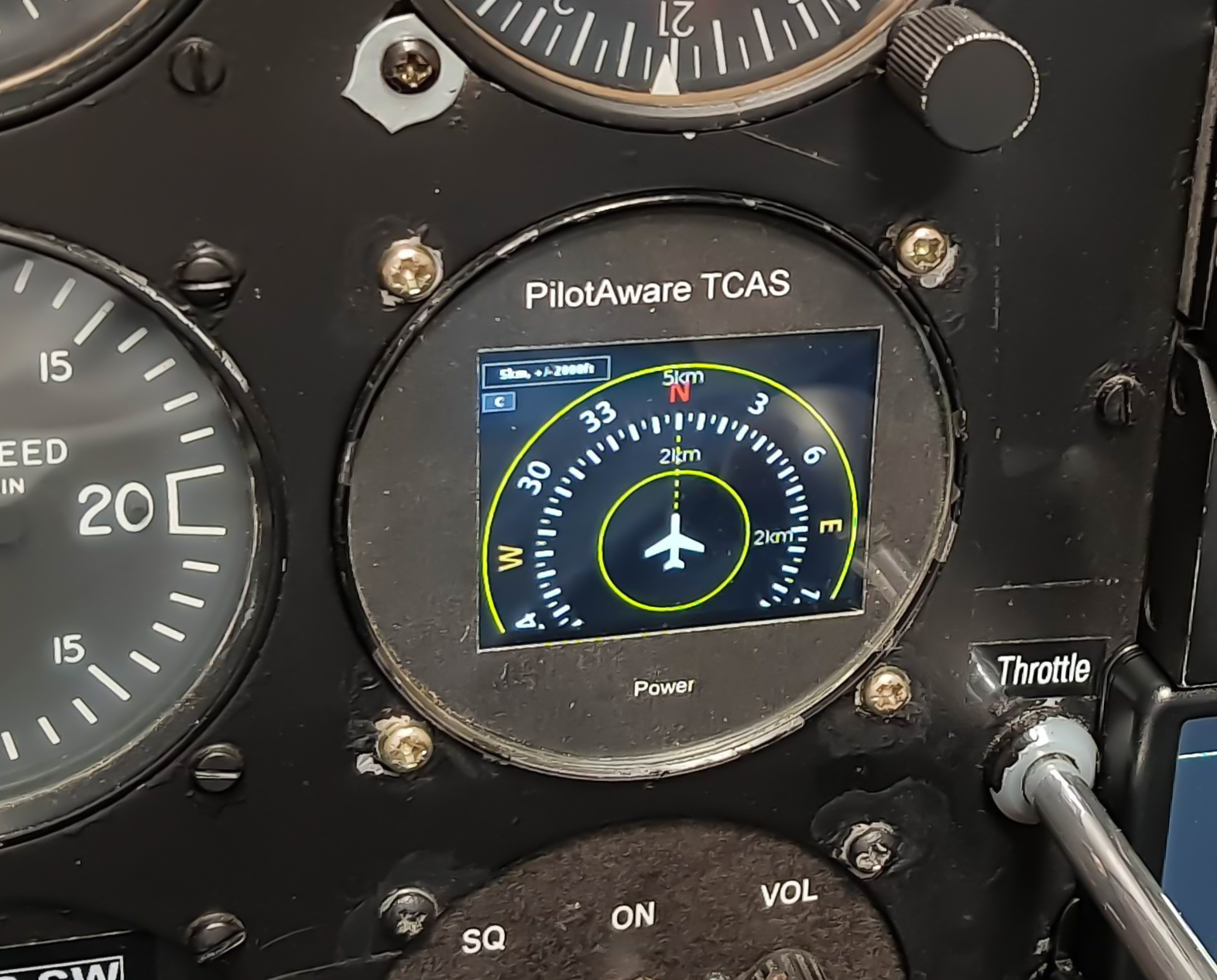
From the pilot’s seat
I wanted to see what it would look like on a real panel, from the pilots seat its lucky that this is a good angle for this screen.
Sunlight
Unfortunately, in sun light the screen reflections are a problem. I looked at anti-glare film and bonding the display to the screen like a smartphone but these are messy solutions.
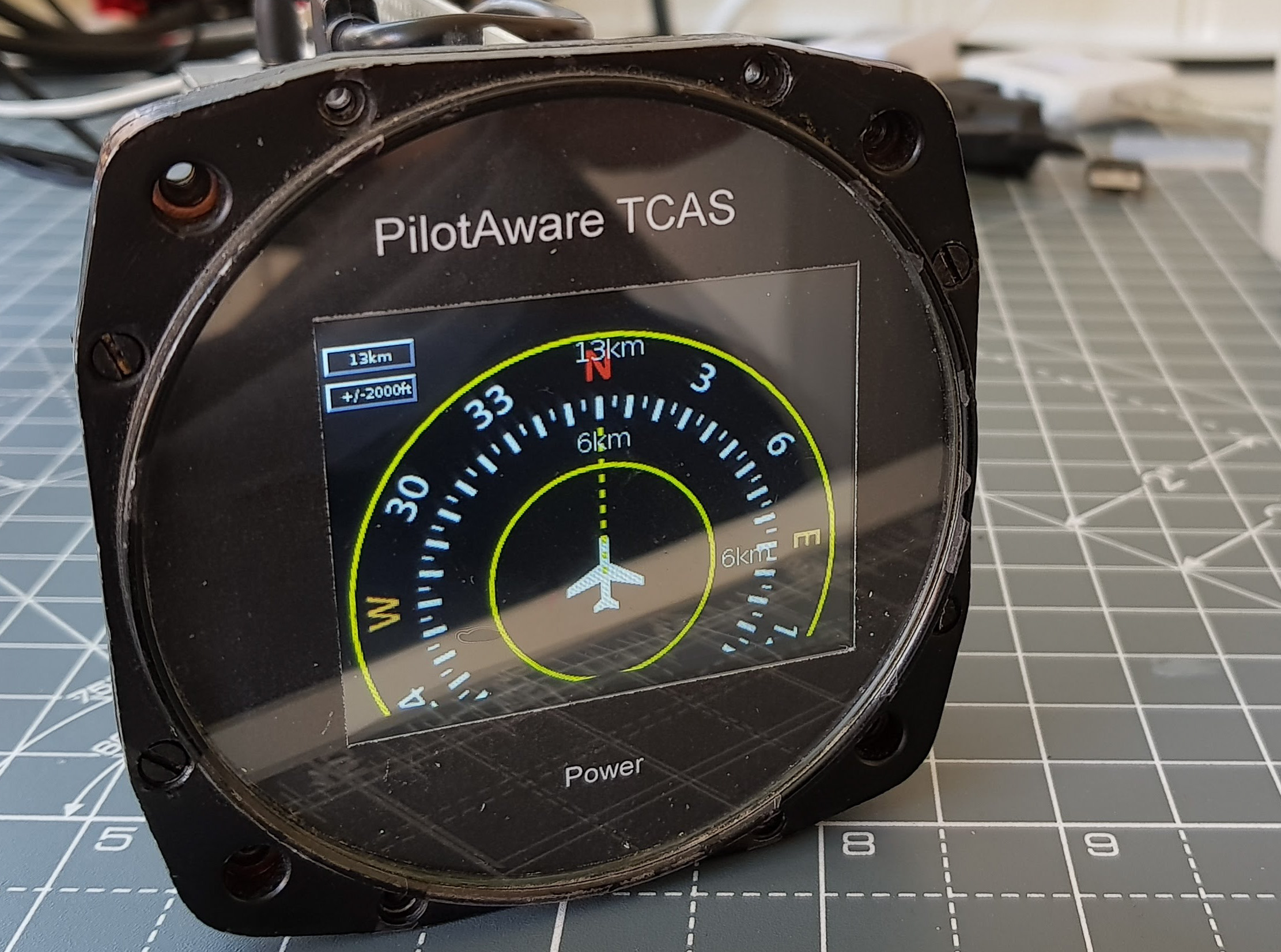
3D printed bezel
What would be better is no glass. I 3D printed a prototype bezel. Shown here was an early prototype. The volume / power knob can now be added as there is no glass to worry about. I also added an LM386 audio amplifier connected to the Pi so you can hear the traffic alerts. Volume / Mute was a must. I scrapped the text and mention of TCAS because it isn’t TCAS, its a traffic aid.
Most connections are made remotely over a 2m cable with a Tesco USB hub. For some reason all sorts of expensive micro-hubs wouldn’t work but a 4 year old one from Tesco’s works perfectly. This allows easy placement of GPS and ADSB receiver at the back of the cockpit out of the way rather than trailing cables all over the place possibly jamming the controls!
I’ve worked hard to ensure that it produces as little radio frequency interference as possible. I have the old non 8khz navcom to play with on the bench and I also have a scope that shows the radio frequencies and strength being emitted so they can be addressed. The power inlet is RF filtered and the case forms a Faraday cage. Additional shielding was still necessary and grounding was a bit of a dark art. In the real aircraft, I realised I probably didn’t need to worry as the existing electrical noise was 3 orders of magnitude higher. There is a lot of electrical noise from the strobe and the alternator, its a wonder any radio navigation equipment works at all.
Final Thoughts
I think this project worked out quite nicely and I learned a lot doing it. It gives you an appreciation for the complexity and radio compatibility issues you can have with airborne systems. My end result with its black panel doesn’t look like its homemade and the performance is remarkable and I tested in the car at the airfield.
Unfortunately, you can’t fix something like this into a certified aircraft – though I’m sure many would. You can place it on the top of the dash although I hat anything obstructing the view – a non-moving dot hiding behind it is exactly what traffic on a collision course looks like.